Modern Hydraulic Power Units: Evolving from Electronic Control into Intelligence
Feb 1, 2011
The advantages and characteristics of electronically controlled lift valves are explored.
Dr.-Ing. E. Goenechea, Bucher Hydraulics AG, Switzerland
This paper was presented at ELEVCON Lucerne 2010, the International Congress on Vertical Transportation Technologies and first published in IAEE book Elevator Technology 18, edited by A. Lustig. It is a reprint with permission from the International Association of Elevator Engineers IAEE (website: www.elevcon .com). This paper is an exact reprint and has not been edited by ELEVATOR WORLD.
Key Words: Hydraulic valve, electronic control, self-teaching, condition monitoring
ABSTRACT
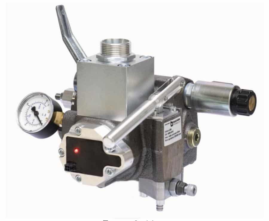
In October 2009 Bucher Hydraulics presented the new electronically controlled lift valve “iValve”. The letter “i” stands for “intelligent” because the valve is not only electronically controlled as its predecessor the LRV-1 is. The iValve also offers some important intelligent features like self-adjustment and condition monitoring realised by its self-teaching capacities called “iTeach”. These features were developed using R&D strategies, tools and capacities that fit highest standards for mechatronic products. In the following the advantages and characteristics of electronic control will be described as well as the influence of the new features. The power of the developed learning algorithms is shown by experimental results.
1. INTRODUCTION
Any hydraulic oil as well as every hydraulic power unit is subject to several physical characteristics. For example the viscosity of hydraulic oil decreases with increasing temperature. This means the oil becomes thinner, the more it is warmed up. For example the viscosity of a typically used mineral oil HLP46 can be about 500 cSt at 2°C and 20 cSt at 60°C.
Another example can be the pump of a power unit. This is typically a screw pump. Due to geometric tolerances these pumps suffer from leakage. This means the volumetric displacement of the pump is dependent on the pressure as well as the viscosity mentioned above.
There is a huge amount of more or less important characteristics of a hydraulic system dependent on various parameters like pressure, temperature, aging of the medium, wear of components, condition of filters and many more.
Sadly these relations are often referred as disadvantages of hydraulic systems. In case of simple mechanic valves they really are. In the following it will be shown that using an intelligent electronic controlled valve these effects can be handled easily and the customer is left with nothing but the advantages of an hydraulic system that lands precisely, drives comfortable and saves as much energy as possible. Many advantages can be named. This paper will concentrate on those deriving from a compact, precise and reliable driving curve – energy efficiency and precise landing.
2. THE MECANICALLY CONTROLLED VALVE
Let us assume that there is a lift travelling between two floors. In order to parameterize the system the technician drives with an empty car and comparatively cold oil. The travel is influenced by the following process (Figure 1).
First the lift is standing still in the lower position. The motor is switched on and the valve is given a signal to drive upwards at full speed. The controlling piston of the valve will move from its idle position (100% circulation) to the driving position (0% circulation). The speed of the controlling piston defines the acceleration as well as the jerk of the car. It is commonly influenced by means of a hydraulic low pass and adjusted by drilling an adjustable orifice. The speed of the car is now defined by several parameters like pressure, viscosity, leakage of the pump and many more as seen before.
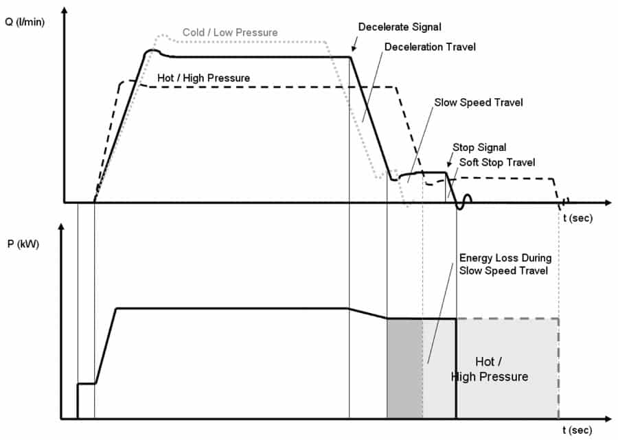
Figure 1. Driving Curves of a Mechanically Controlled Valve
As the car passes a switch which is at a certain distance to the upper stage the signal changes from “full speed” to “slow speed”. This causes the valve to decelerate the car down to slow speed by opening circulation for most of the volumetric flow. The deceleration as well as the exact slow speed is dependent on the named parameters. Slow speed means the car drives at e.g. 10% of its full speed while 90% of the volumetric displacement of the pump is delivered against the cylinder pressure and directly lead back to the reservoir.
This situation is kept until the car passes the next switch. Now the cabinet signalizes “stop” to the valve. Some mechanical valves stop abruptly others possess mechanical means to realize a so called soft stop. The distance from stop signal to the final standstill is dependent on the well known parameters again.

Figure 2. iValve
The technician has parameterized the mechanical valve. He has adjusted 10 or more screws driving upwards and downwards many times. The car is still empty. The oil is comparatively warm. He must have taken two things into account. On the one hand the lift can be used at lower temperatures than he has adjusted now. In this case the displacement of the pump will be higher and the deceleration will take longer. Thus it will take a longer way to stop. The technician has to adjust a slow speed time long enough to compensate this effect otherwise the lift will pass over the landing position and have to take back. On the other hand if the car is fully loaded and/or the oil is hot full speed will be significantly slower. With the chosen adjustment the car will decelerate in a much shorter time and it will need to pass a long distance in slow speed wasting a lot of energy – energy that will heat up the oil even more. Obviously the dependency of acceleration and deceleration from viscosity as well as the simplicity of the hydraulic control lead to comfort issues like jerk and vibrations.
3. THE ELECTRONICALLY CONTROLLED VALVE
The most powerful mean to minimize energy loss caused by the named characteristics of hydraulic power units is to guarantee a fast start, high acceleration and deceleration and a short slow-speed-phase independent from load and temperature.
This can be achieved using electronic control. Let us assume that there is a valve that is able to adjust any volumetric flow upwards and downwards. Added to this there is a volumetric flow sensor that measures the adjusted flow running through the valve. With these components you can design a system that controls the car movement in a much more sophisticated way than a mechanical Valve can do. For example you can design a driving curve that guarantees minimal jerk and vibration at maximum acceleration and deceleration. The driving curve shows the volumetric flow (resp. car-velocity) as a function of time. Whereas characteristic points like start of deceleration and soft-stop are triggered by the position of the car inside the shaft.
The technician can set the deceleration-point much closer to the stop-position because the lift can decelerate much faster without annoying effects. Adding to this the car will maintain the same deceleration unaffected by the car load or oil temperature. So the technician can adjust the slow-speed-phase very short. The energy wasted in this phase of the travel can be reduced significantly. Once he has installed the switch for stop signal he adjusts the deceleration so that the car reaches slow speed shortly before it reaches the soft-stop switch. Also the travel from the soft-stop signal to the stop position is very independent from car load and temperature. Once adjusted it varies about +/- 3 mm in the case of the Bucher Hydraulics LRV-1.
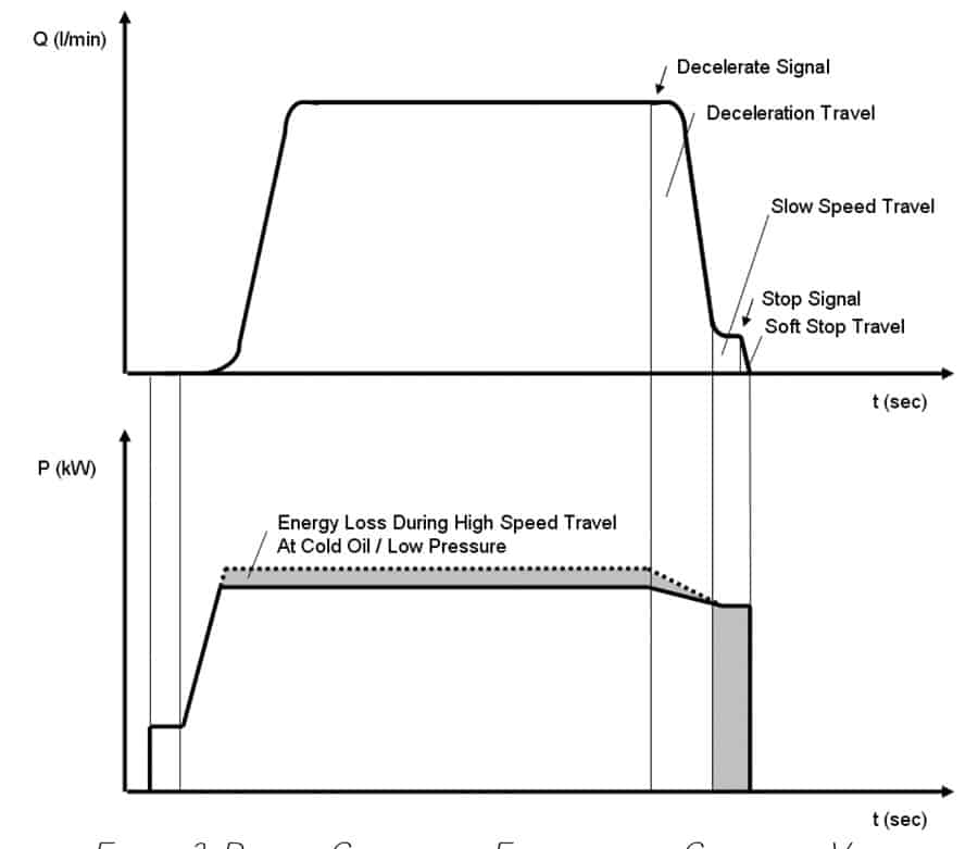
Figure 3. Driving Curve of an Electronically Controlled Valve
4. THE INTELLIGENT VALVE
These quality standards described above are common for discerning customers. The stop accuracy of +/- 3mm and a slow speed phase between 0.5 sec and 1 sec can be achieved when using an electronically controlled valve as it is sold for several decades.
4.1 iTeach
An intelligent valve is supposed to improve the system characteristics of an electronic valve to the maximum. Comparing Figure 1 with Figure 3 you realise, that the electronic valve saves up to 30% of the energy needed for an average travel of a hydraulic lift by shortening the average slow-speed travel significantly. In this phase most of the avoidable energy-loss is suffered. To afford this, the high speed is kept constant for all operation points. As seen before the volumetric displacement of the unit is a function of parameters like car load and oil viscosity. So the chosen velocity must be the slowest velocity that is possible for the loaded car and lowest viscosity. This means that driving upwards with empty car and/or cold oil a certain percentage of the volumetric displacement of the pump flows off unused. This situation is ended with the intelligent valve. It controls the high-speed velocity to the maximum of the volumetric displacement of the pump at all operation points of the hydraulic system. But the car shall still decelerate at a driving curve that minimises the energy consuming slow-speed phase to the minimum. This is realised by one aspect of its “iTeach” – capacities. iTeach is a conglomerate of self-teaching algorithms that enable the iValve to get to know the connected hydraulic system and adapt to its behaviour. In the case of the systems high-speed velocity iTeach is able to realise, when the velocity of the accelerating car reaches its maximum which is dependent from the named parameters like oil viscosity, car load, motor revolution speed and many more. The algorithm learns the reached velocity as a function of temperature and system pressure. After some travels it is able to head directly for the systems maximum speed with increasing precision. Using this algorithm the iValve is able to use all of the hydraulic power generated by motor and pump. But the upwards full speed will now be a function of the named parameters. If the car decelerates from different velocities using the same driving curve parameterisation it will cover different distances. To avoid this and to realise a minimum slow-speed phase for all operation points it is necessary to adopt the driving curve to the actual velocity.
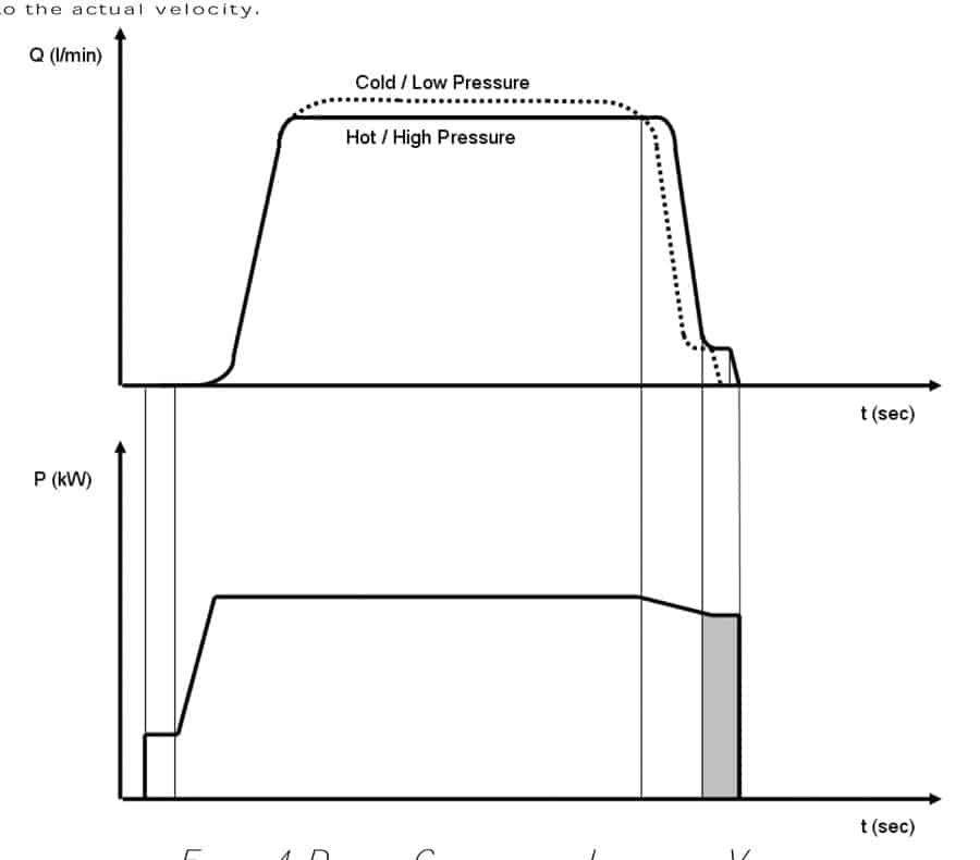
Figure 4. Driving Curves of an Intelligent Valve
A second iTeach capacity is needed to make this possible. If a car travels at a certain high speed there is a minimum deceleration stroke known by technicians and named in the manual. The valve is factory set to this deceleration to avoid it from passing over. If the shaft is not constructed to the maximum the car will decelerate too fast and have to drive at slow speed longer than necessary. At this moment iTeach will learn the real geometric distance between the deceleration switch and the soft stop switch.
When next time the car is travelling with high speed and the deceleration signal is given, iTeach will calculate the necessary deceleration curve in real time in order to reach the soft-stop position with minimal slow-speed phase. For this it will use the learned distance between the deceleration switch and the soft stop switch as well as the actual velocity deriving from the high speed optimisation.
Due to these intelligence features the valve will make the car drive at the highest possible velocity enabled by motor and pump as well as it will decelerate following the optimal driving curve with minimal slow speed phase and come to rest at the floor level with minimum distance – independent from car load, oil and room temperature or other parameters like age of the system and many more (Figure 4).
4.2 Condition Monitoring
The integration of intelligence into an electronically controlled valve makes it possible to disburden the technician from duties like parameterization, adjusting maybe readjusting or optimization. But integrated intelligence can afford even more. Via the methods of Condition Monitoring it is possible to observe and analyse the state of the hydraulic system and evaluate or even forecast the condition of single elements like filters, the medium and many more.
These features will be developed in a second step of the iValve launch. In cooperation with selected partners data will be collected from iValve driven hydraulic lift units to realise what is described below.
In order to realise the intelligent features of the iTeach algorithms the electronically controlled valve is already equipped with a volumetric displacement sensor, a pressure sensor and a thermal sensor on the hydraulic side. Adding to this it possesses sensitivity on the electronic side as it controls the electric current to the proportional magnet for example.
A huge amount of information is gathered by this package of sensors and fed to a virtual model located
in the valve. The model represents the valve and the hydraulic system which is connected. It can be represented similar to a simulation model of the monitored system and realises if parameters of the system drift or change.
Finally conclusions can be drawn from the model concerning the state of single elements of the valve or the system. Warnings and recommendations can be given when filters shall be cleaned or the oil shall be changed.
5. EXPERIMENTAL RESULTS
The algorithms described in chapter 4 where examined using a test lift at Bucher Hydraulics in Neuheim. A prototype of the iValve 250L was connected to the hydraulic system of a 2:1 plunger cylinder driven lift powered by a 250 l/min screw pump and an adequate asynchronous motor. The controller of the valve was replaced by a LabVIEW controlled DAQ-Board. Tests have been executed in the operation parameter field between of the iValve. Temperature: 2°C – 60°C Static Pressure: 12 bar – 60 bar.
Thanks to a position measuring system all switch points can be set digitally and the position of the cabin can be controlled by mm.
Exemplarily two learning processes are shown in the following. In the first example the lift was travelling upwards with maximum speed of 250 l/min (0.6 m/sec) at a static pressure of 30 bar. The deceleration distance was set to 0.8 m. Slow speed is 20 l/min and the soft stop distance was chosen to be 20 mm. This soft stop distance is comparably long and was chosen to analyse a worst case. Often the soft stop distance is set to 10 mm. In Figure 5 the error of the landing position is plotted against the number of executed travels. Factory setting is a very fast stop. Therefore the lift will stop too short and it will come to hold 8mm before the correct stop position. After the 3rd travel the learning algorithm goes below the target error of +/- 3mm.
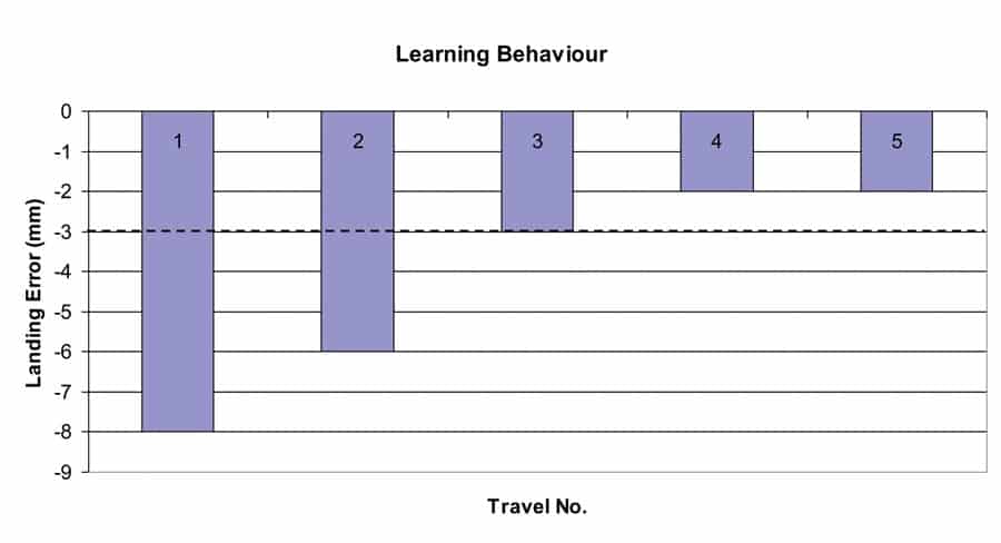
Figure 5. Learning Landing Precision at Soft Stop Distance 20mm
Another example is given in Figure 6. In this case the car travelled upwards. The static load was 12 bar. High speed is 250 l/min, low speed is 20 l/min. The deceleration distance is 0.8 m. The deceleration presetting is very high. So that during the first travel the lift will decelerate too fast, and it has to travel at low speed for a while until it reaches the soft stop switch. After the first travel the algorithm learned the deceleration distance and in the second travel it already reaches the target setting of 0.7 sec of slow speed travel.
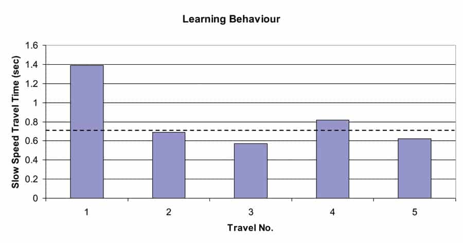
Figure 6. Learning Slow Speed Travel Time Set to 0.7sec
6. CONCLUSION
An hydraulic lift is triggered by several signals given by the control cabinet. These signals are defined by the geometric position of switch points in the shaft. Between these points the car is supposed to accelerate, decelerate, drive and stand still with certain velocities, accelerations and low jerk. In a mechanical valve these characteristics are dependent from temperature, car load and many more. Therefore a mechanical valve has to be adjusted to a long and energy-consuming slow speed phase and still the landing precision is low.
An electronically controlled valve is very independent from the operation points. Therefore it can be adjusted much closer to the optimal driving curve saving energy, landing very precise and driving comfortable. Still these adjustments have to be done even though the user interface of an electronically controlled valve is much more comfortable than the abstract screws of a mechanical valve.
An intelligent valve is able to analyse the hydraulic system of a lift and to adjust itself. After installing the lift mechanically, the intelligent valve will drive with a secure factory setting. After a few travels it will learn the real characteristics of the connected lift system and adjust itself to the optimal driving curve.
Get more of Elevator World. Sign up for our free e-newsletter.

