New Design Provisions for Anchor Channel Fastenings According to CEN
May 1, 2013

Hilti Corporation, Principality of Liechtenstein
This paper was presented at  USA 2012, the International Congress on Vertical Transportation Technologies and first published in IAEE book Elevator Technology 19, edited by A. Lustig. It is a reprint with permission from the International Association of Elevator Engineers
  (website: www.elevcon.com). This paper is an exact reprint and has not been edited by ELEVATOR WORLD.
Key Words: Anchor channel design, ETA, fastening system, failure load, fatigue
Abstract
Architects specify cast-in anchor channels as an alternative anchoring method. Design principles based on the German National Approval (DIBt) date back to the early seventies and are based on steel failure. The new European Code CEN-TS 1992-4-3 comprehensively covers anchor channel design featuring partial safety factors and design flexibility through use of various parameters. This paper discusses the structural differences in the two design concepts. The verification procedure for anchor channel design is also briefly described. Lastly, the benefits in terms of additional safety and cost efficiency in rail and door fastening are explained.
1. Introduction
Over the past 10 years or more a concept for the design of post-installed anchors has become established which, in contrast to the greatly simplified concept previously in use, allows a significantly more detailed approach to the stress situation. This concept makes it possible to represent in detail not only the external forces acting on the anchors but also the anchors’ resistance to the applicable stresses. Comprehensive tests take into account the probability of anchor failure in the base material for the following three possible failure categories:
- Steel failure: the material from which the anchor is made fails due to the stress applied to it
- Functional failure: the anchor’s anchoring principle fails due to the stress applied to the anchor
- Base material failure: the base material in which the anchor is set fails due to the stress transferred to it
Uncertainties in the approach to detailed stress and resistance factors are taken into account by partial safety factors. The greatly simplified design concept previously in use, based on the state of the knowledge of this subject in the seventies has been superseded by a more complex procedure incorporating advances made in anchor theory and test technology. The need for more demanding calculations is compensated through use of the latest computer software. It is thus now possible for architects and construction engineers to design a more cost-efficient and safety-optimized anchor arrangement in a relatively short time. This up-to-date anchor design concept has been developed by EOTA, the European Organisation for Technical Approvals, and its implementation is supported by all European anchor manufacturers.
Similarly, anchor channel design also follows a greatly simplified design concept. This detailed design concept based on partial safety factors has also been available for anchor channels since 2010. Used by various anchor channel manufacturers, it is already in the implementation phase. When developing its own range of anchor channels Hilti decided that it stood to reason that the design principles used should be in line with the already familiar state-of-the-art detailed design concept incorporating partial safety factors.
The following paragraphs summarize the differences between the two design concepts in use today and take a detailed look at the up-to-date concept.
2. Anchor Channel Design Based On The Existing DIbt Approval For Cast-In Anchor Channel
The DIBt approval (Deutsches Institut für Bautechnik) suggests use of a simplified selection aid that is oriented towards the maximum tensile and shear loads that can be taken up by the anchor channel in the concrete.
This simplification is based on the assumption that external forces acting on the channel can be consolidated. All forces acting on the object are viewed as single forces or in pairs spaced at a distance of ≥100mm (for channel size 28/15). All forces acting on the object are regarded as tensile forces so long as they act at an angle of less than or up to 15°. At an angle of 15° a sudden rise in the permissible load is observed. The simplified choice available splits the channel into individual spans which are anchored by two anchor bolts, each positioned at a minimum of 25-35mm from the end of the channel. For the design it makes no difference whether the tensile force acts on the channel centrally between two anchor bolts or directly over one bolt. These simplifying assumptions result in the maximum stressing forces being taken into account in the form of rigid load classes (= steel failure). The maximum load values are given for one or a maximum of two concrete strength grades per channel profile size. With reference to the material in which the channel is anchored, the values for edge distance, channel spacing and concrete thickness are also given. Values below these should not be used if the maximum loads stated in the approval are to be applicable.
Categorization of loads in load classes and the similar design of the various types of anchor channels available result in all products of the same geometry having the same maximum permissible loads. The design process is straightforward and the procedure for checking the equality of competitors’ products for the required specification can be carried out efficiently. On the other hand, this greatly simplified design process, based on only a few tests which do not take the behavior of the base material under load adequately into account, carries the risk in some cases of producing an unsafe, underdesigned system or, conversely, resulting in overdimensioning and thus poor cost-efficiency.
In addition to this, in the German DIBt approval the instructions for taking alternating loads into account in the design are also presented in simplified form.
3. Anchor Channel Design Based on the ETA European Technical Approval
The design concept introduced by the EOTA reflects the current state of knowledge on this subject and takes safety into account through use of partial safety factors. In doing so, the failure modes currently known to us are taken into consideration and verified individually. External forces acting on the system are taken into account for each T-head bolt individually as separate tensile and shear forces. For the channel itself the resistance of the fastening system to various types of failure is also determined under load in elaborate tests. The influence of edge distance, load position, structure thickness, concrete grade, channel dimensions and additional steel reinforcement are analyzed and, furthermore, detailed reduction factors allow use of the design process even in cases that lie beyond the scope of the rigid conditions set by the DIBt approval.
The EOTA has defined guidelines for the design of anchor channels (CEN/ TS) and, in the associated Common Understandings of Assessment Procedures’ (CUAP), described in detail the evaluation procedure that leads to the resistances, partial safety factors and reduction factors used in the design process.
The process thus gives much more detailed insight into the load and resistance situation applicable to the anchor channel fastening. The number of factors to be taken into account result in a more complex calculation, but thanks to today’s PC software, this can be carried out efficiently.
The detailed design procedure results in specification of a safe, cost-efficient anchor channel fastening, including possible reduction of structural component thickness and edge distances. At the same time, this method of design based on the current state of knowledge allows the greatest possible safety with regard to correctness.
4. Evaluation of Acting Loads In Accordance With ETA
First of all, the forces acting on the various T-head bolts are split into their tensile and shear components. The acting forces are separated into own weight, superimposed loads, alternating loads and each type of load is assigned its own (partial) safety factor.
The channel is viewed as a system in its entirety. The forces acting on the T-head bolts are then determined. The idea of considering parts of the anchor channel separately is replaced by a holistic approach. Using the triangular load distribution method and with the aid of the intersecting lines theorem, load distribution over the entire anchor channel is assessed in the form of an envelope curve. At the same time, the positions on the channel at which the forces are acting are also taken into account (directly over or between two anchors).
With several T-head bolts plus different tensile and shear forces involved, the evaluation process becomes complex, especially when a system of static loads consisting of own weight and superimposed loads is acting on the fastenings. This, however, is compensated through use of advanced PC software. The envelope curve for the total load on the channel forms the basis for detailed determination of the various forces acting on the parts.
Evaluation Of Anchor Channel Failure Mode According to ETA
In a second step, the anchor channel’s resistance to various types of failure is determined individually according to tensile stress or shear stress. Verification is provided for three main types of failure:
- Steel failure: the material of the T-bolts, the anchor channel or the anchor bolts attached to the channel gives way due to the stress applied to it
- Base material failure: various failure modes in reaction to stresses acting on the base material
- Additional reinforcement: failure of supplemental steel reinforcement or the connection to the supplemental reinforcement supporting the load
Suitable test procedures are used to investigate the three main failure categories in detail, as defined in the CUAP. The following table provides a detailed overview of the types of failure evaluated in accordance with EOTA CUAP.
Resistance to a certain type of failure is expressed in the percentage utilization of the anchor channel system as far as this specific type of failure is concerned.
The degrees of utilization determined can be combined for each type of failure in a limiting curve and added to a diagram showing resistance to tensile and shear loads. The three curves then show clearly which type of failure will occur when a certain limiting value for a defined combination of tensile and shear loading is reached. As these curves are derived directly from the test results they will be different for the various products from various competing manufacturers. Differences in the quality of the various competing products will thus be more apparent and, on the other hand, this detailed knowledge will allow more flexibility in optimizing anchor channel fastenings for greater resistance to certain types of failure.
5. Evaluation of the Resistance of the Anchorage
The design process verifies that the anchor channel’s determined resistance to the specific type of failure is greater than the calculated stresses. It verifies that the anchor channel system’s degree of utilization for the type of failure calculated is less than 100%.
This verification is already familiar to us from anchor design and the degrees of utilization are, for example, given as results in the Hilti PROFIS Anchor Channel design software.
The design process for static loads is carried out on the basis of detailed information about stress and resistance. The anchor channel system can thus be designed cost-efficiently with great certainty and, at the same time, with a high level of safety, i.e. resistance to failure.
6. Taking Fatigue Loading Into Account in Accordance With the EOTA Guideline
With regard to design for cyclic loading, the new design concept offers a number of new features that result in a conservative and thus safe design. The differences between the new concept adopted by the EOTA and the concept according to DIBt are described here briefly.
One major difference is that the tests in accordance with the DIBt concept are applied to the anchor channel attached to the anchor bolts, in which the alternating loads act directly over the anchor bolts. In contrast to this, with the future EOTA CUAP method, the tests are carried out on anchor channels set in concrete. Furthermore, the failure load is determined for cyclic loads acting directly over the anchor bolts as well as for cyclic loads acting in the middle of a span between two anchor bolts, thus allowing bending of the anchor channel as a possible cause of failure. The lowest of the failure values is used for the design.
A further significant difference between the current and future test procedures for cyclic loads is that, with the current concept, the definition of failure is breakage of the fastening, whereas with the future EOTA CUAP concept failure due to cyclic loading is defined as being the first signs of damage to the anchor channel system. This approach is considerably more conservative and will lead to a great reduction in the value for resistance to cyclic loading.
The third section discusses the subject of changing how the combination of cyclic and static loads is taken into account. The current design concept for cyclic loads defines a maximum cyclic load stress range for each anchor channel profile, corresponding to its fatigue strength. The stress range is deducted from the maximum tensile load defined in the load classes and the remaining value then indicates the resistance to additional static tensile loading. The concept discussed in the EOTA makes provision for defining the resistance to cyclic loading by way of a Goodman diagram as a function of the expected number of cycles and taking resistance to cyclic loading over a period of time into account.
This approach results in better utilization of the anchor channel system while maintaining an adequate safety level for all load combinations. It thus achieves more cost-efficient dimensioning and greater safety because the design is based, in accordance with the state of the art, on the actual loading situation while its resistance to failure is based on the situation with the greatest probability of occurrence. Accordingly, the tests are carried out on a cast-in channel (i.e. already set in concrete), including a test with a load placed at the center of a span between two anchor bolts. Moreover, if the anchor channel system suffers damage that restricts its further use it is deemed to have failed the test.
7. Conclusions
The new design concept for cast-in anchor channels, favored by the EOTA and by Hilti, follows in the footsteps of the anchor design concept with partial safety factors that has been established and in use for more than 10 years. Development of the concept has been driven by comprehensive tests and the latest knowledge of the subject. It is thus state-of-the-art in terms of anchor theory and the techniques used for the failure tests.
As with anchor design, the new design concept results in a constant safety level for all parameter combinations and cost-efficient dimensioning of the anchor channel solutions. The more complex calculation procedure required is compensated through use of the latest advanced PC software. Design in accordance with the partial safety factor concept is based on very detailed knowledge of the loading situation and the system’s resistance to various types of failure.
Design for cyclic loads follows a model that is significantly more conservative than the model currently in use, as the first signs of damage to the anchor channel system are already classed as failure.
On the basis of experience gained with modern design concepts in the field of anchor fastening technology it was clear to Hilti that the development and introduction of its new range of anchor channels would be centered solely on the most up-to-date, state-of-the-art design concept and that appropriate support would be given to the approach incorporating design for cyclic loading.
Use of the latest, advanced PC software will reduce the amount of work that users of these products are required to invest with the changeover to the new design concept. Hilti will, of course, also support its customers in the changeover process by providing the appropriate training through its teams of technical specialists and engineers.

Figure 1: The load data table from the German DIBt approval 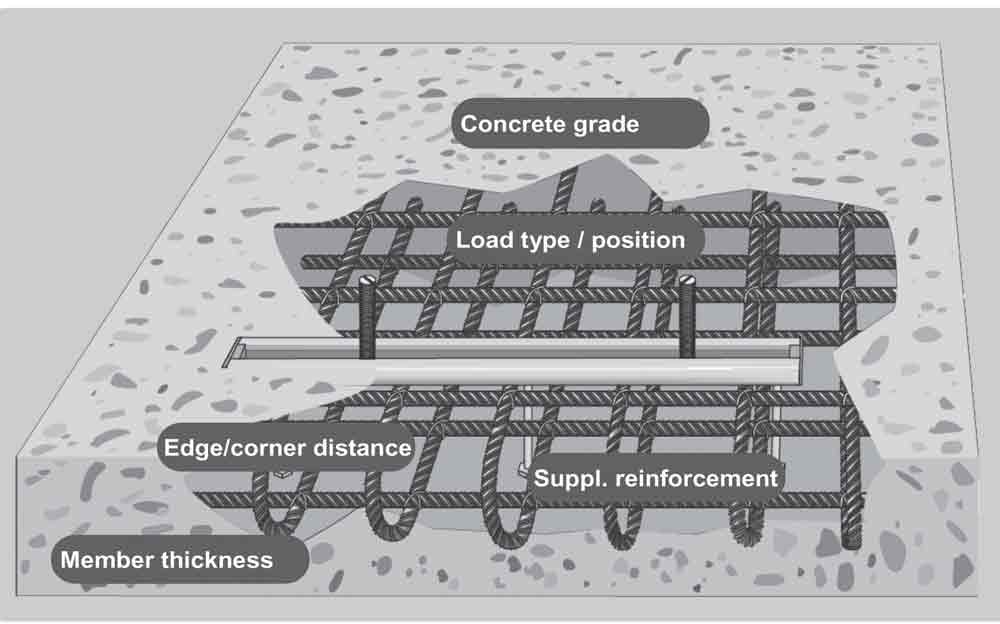
Figure 2: Factors influencing load resistance 
Figure 4: Determination of the loads acting on the T-bolts and the channel 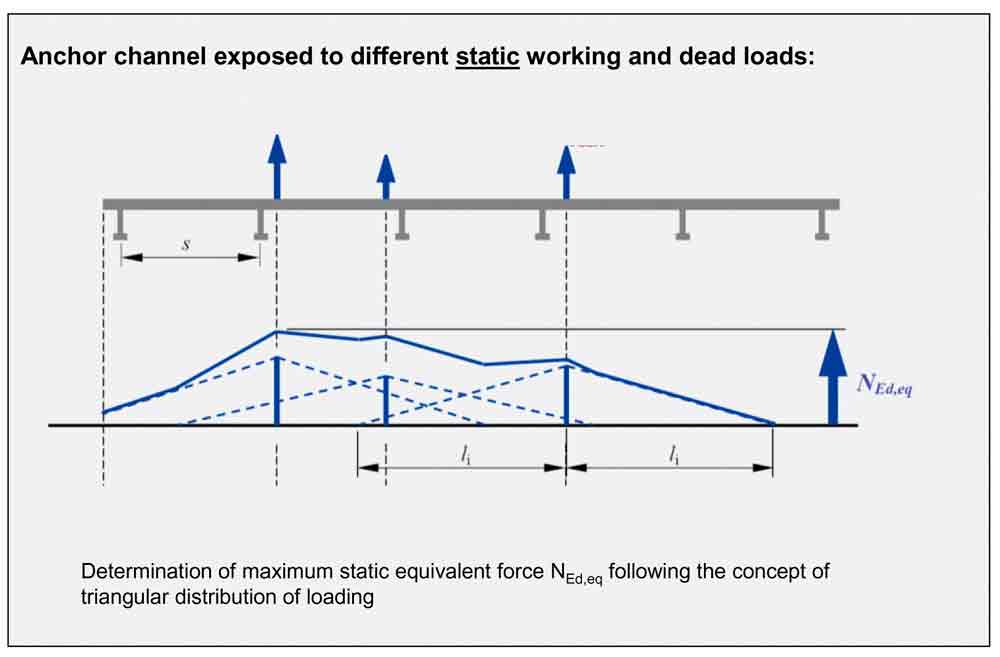
Figure 5: Determination of the loading curve as a combination of all acting loads 
Figure 6: Possible failure modes for cast-in anchor channel 
Figure 7: Combination of tension and shear resistance for different failure modes 
Figure 8: Determination of cyclic loads acting on the anchor bolts 
Figure 9: Determination of combined static and cyclic loads acting on the channel 
Figure 10: Design concept for combined static and dynamic loading
REFERENCES
(Hilti HAC 2011) M. Heudorfer; H. Basche; The New ETA Approval for Anchor Channel
(Elevcon 2006 – Elevator Technology 16) M. Merz (2006). Dynamic Design for Elevator Anchoring in Buildings
Get more of Elevator World. Sign up for our free e-newsletter.