New Indian Standard IS 17615
Aug 4, 2022

On measurement of ride quality for lifts, escalators and moving walks
Abstract
The Indian Standards (IS) on lifts have been in existence for many years. The current series of Lift Standards, namely IS 14665 Part 1 to Part 5, was published in the years 1999 to 2001 replacing the then-current standards IS 4666, IS 1860, IS 3534, and other component standards. The Indian Standards on Special lifts (e.g., lifts for Persons with Disabilities, Hydraulic Lifts, Home lifts, and Machine-Room-Less lifts, etc.) were added subsequently. Now, another big revision to the lift standards based on ISO 8100-part 1 and ISO 8100-part 2 is in the offing. While a lot of new Indian standards were recently published, such as SNEL, EMC Guidelines, Energy consumption, PESSRAL/PESSRAE, etc., there was a need to define ride quality measurement criteria to benefit the lift industry by reducing variability in the results of lift, escalator and moving walk ride quality measurements.
Introduction
The vertical-transportation (VT) industry in India has been largely regulated by the State Lift Act & Rules. As of now, there are 11 states and one union territory that have enacted their own Lift Act and framed Rules thereunder. In addition, the Bureau of Indian Standards (BIS) published several Indian Standards on Lifts and Escalators more than 30 years ago. Typically, the Indian Standards are voluntary in nature. A few standards are made mandatory for the BIS mark to protect consumer health and safety, and a few others are covered under the compulsory registration scheme. However, some states (e.g., Kerala, Tami Nadu, Karnataka, Jharkhand, and Haryana) have incorporated clauses in their respective Lift Act and Lift Rules, making compliance to the relevant latest Indian Standards on the Lifts and Escalators compulsory. Lifts and escalators get regulated through the National Building Code of India, as well. New Indian Standards IS 17615-1:2021 and IS 17615-2:2021 were released by BIS, and this article will guide users on measurement of ride quality for lifts, escalators and moving walks to benefit the lift industry by reducing variability in ride quality results caused by differences in methods and tools used.
Background
The measurement of elevator ride quality (frequently called ride comfort) has become an important subject over the past several years. It is now often part of specifications for new and modernized elevator systems. It is also a competitive issue for elevator manufacturing, installation and maintenance companies because it is a strong indicator of the quality of design, installation and service of elevator systems. More than that, the analysis of vibration and sound that has been collected for ride quality measurements provides the ability to diagnose the function of elevator and escalator system components.
How ride quality is measured strongly affects the results of those measurements. Based on extensive work that was performed by companies from around the world, a new Indian Standard IS 17615 was released for the measurement of elevator, escalator and moving walk ride quality. The new standard IS 17615 Parts 1 & 2 are identical with international standards ISO 18738-1 Lifts (elevators) — Measurement of ride quality — Part 1: Lifts (elevators) and ISO 18738-2 Measurement of ride quality — Part 2: Escalators and moving walks.
Overview
Along with the development of new lift technologies, specifications for lift, escalator and moving walk installations have become more and more detailed. Since the provision of lifts, escalators and moving walks had become an indispensable requirement in buildings, malls, etc., their performance has been receiving increasing attention, and passengers expect increasingly better riding comfort.
At present, a lift or escalator’s performance is usually evaluated based on time taken to perform its function as VT. This includes time required to close the doors (lifts), start, move, stop and open the doors (lifts). To accomplish these actions, some level of noise and vibrations will be generated. These are then perceived as ride quality by the passengers. However, the most important aspect of ride quality is how to quantify it by defining what exactly ride quality is, how it is measured, the tools to be used and how it is to be interpreted. The objective of this part of IS 17615:2021 is to encourage industry-wide uniformity in the definition, measurement, processing and expression of vibration and noise signals that comprise lift ride quality. The aim of such uniformity is to benefit the lift industry by reducing variability in the results of lift ride quality measurements caused by differences in the methods of acquiring and quantifying the signals.
Part 1 & 2 of IS 17615 are intended to be referred to by those parties interested in:
- developing manufacturing specifications and calibration methods for instrumentation,
- defining the scope of the specifications for ride quality in contracts, and
- measuring ride quality for lifts, escalators and moving walks in accordance with an Indian Standard.
It is intended to produce ride quality measurements methods and results, which:
- are simple to understand without specialized knowledge of noise and vibration analysis,
- correlate well with human response to ensure acceptability, and
- are accountable via calibration procedures, which are traceable to national standards.
Measurement of Lift Ride Quality
Measuring instrumentation shall consist of the following:
- transducers to measure acceleration in each of the three orthogonal axes
- a transducer to measure the sound pressure level
- data acquisition system
- data storage system
- data processing system
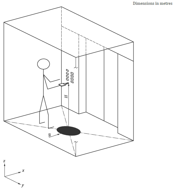
Location of transducers: Transducers for the measurement of vibration shall be placed on the car floor within a 100-mm radius of the center of the floor (Figure A). The transducer for the measurement of sound shall be located 1.5 m ± 0.1 m above the same region of the floor, aligned along the x-axis, and aimed directly at the front car door. Not more than two persons shall be present in the lift at the time of taking measurements.
Evaluation of ride quality consists of the following:
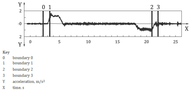
- Boundaries of calculation. The following boundaries shall be used to define the regions over which signal quantities are calculated:
- Boundary 0 at least 0.5 s before commencement of door closing at the departure terminal floor.
- Boundary 1500 mm after commencement of lift motion from the departure terminal floor.
- Boundary 2500 mm before cessation of lift motion at the arrival terminal floor.
- Boundary 3 at least 0.5 s after completion of door opening, or cessation of lift motion, at the arrival terminal floor, whichever occurs last.
- Acceleration and deceleration measured in m/s2: The values of acceleration and deceleration shall be calculated by applying a 10 Hz low-pass filter to the unweighted z-axis signal, as shown in Figure 1. The 10 Hz low-pass filter shall be a 2-pole Butterworth filter.
- Jerk measured in m/s3: This is the rate of change of acceleration.
- Vibrations measured in mgal: The vibration signal shall be evaluated for peak-to-peak levels. The maximum peak-to-peak vibration level is the largest of all the peak-to-peak values found between defined boundaries. The A95 (typical) peak-to-peak vibration level is that value that 95% of the peak-to-peak levels, between defined boundaries, are equal to or less than.
- Horizontal vibration (x- and y-axes): The peak-to-peak vibration levels of the weighted x- (Front-back) and y-axis (sideways) shall be calculated.
- Vertical vibration (z-axis): The peak-to-peak vibration levels of the weighted z-axis shall be calculated.
- Velocity measured in m/s: The value of velocity attributed to motion control shall be measured directly or calculated by integration of the 10 Hz low pass filtered signal.
- Sound measured in dBA: The maximum sound pressure levels between doors start to close to doors fully open shall be calculated.
Measurement of Ride Quality for Escalators and Moving Walks
Measuring Instrumentation shall consist of the following:
- a transducer to measure acceleration in each of the three orthogonal axes combined with a data acquisition system
- a transducer to measure sound pressure level and/or sound intensity level
The escalator or moving walk should be measured in both running directions, except where the unit is designed to operate in one direction only. In this case, it is sufficient to measure the unit only in this direction. The measurement shall be carried out under the following conditions. The unit shall:
- be assembled completely, adjusted and operating in accordance with the operating manual
- have reached normal operating temperature
- be measured in an unloaded condition
- be measured after the starting sequence has been completed. If the unit operates at different speeds, all speeds shall be measured. This refers only to speeds for passenger transportation.
- have finished star/delta change over, if used, before starting the measurement. This is to avoid faulty measuring values.
Procedure for Load Carrying Unit Vibration Measurement
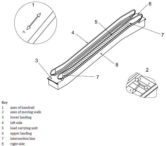
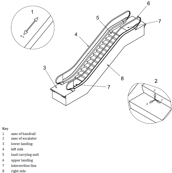
- Apply the transducer or measurement device on the centerline of the load carrying unit (Figure 2) of the running escalator or moving walk after passing the intersection line between the load-carrying unit and the landing.
- Align the axes of the transducer to the axes of the entire escalator or moving walk (Figure 2).
- The transducer or measurement device shall remain in stable contact with the measuring surface throughout the measuring process. A contact pressure on the measuring surface of not less than 60 kPa is required, which is approximately the pressure of a human foot.
- The operator shall stand on the step/pallet tread surface directly behind the step/pallet being measured. In the case of a belted load carrying unit, the operator shall not stand within 300 mm of the transducer.
- Start the measurement immediately after the transducer is placed for a horizontal moving walk.
- Start the measurement at the beginning of the inclined area for an escalator or an inclined moving walk.
- Stop the measurement as close as possible to the opposite landing for a horizontal moving walk.
- Stop the measurement just before the inclined area intersects the transition curve for an escalator or an inclined moving walk.
Procedure for Handrail Vibration Measurement
- Apply the transducer on one of the handrails of the running escalator or moving walk in the landing area.
- Align the x-axis of the transducer to the xh-axis of the handrail (Figure 2).
- Fix the transducer by hand.
- Start the measurement at the beginning of the inclined area for an escalator or inclined moving walk or directly after fixing the transducer to the handrail for horizontal moving walks.
- Stop the measurement at the end of the inclined area or upon passing above the intersection line between the landing and the load carrying unit for a horizontal moving walk.
Repeat the procedure for the second handrail.
Sound Measurement
The sound level measured at the specified positions defined below determines the ride quality experienced by the passenger relative to noise levels. The measured sound level is the sum of:
- emission sound level of the escalator or moving walk
- background noise level
- acoustic characteristics of the room where the unit is installed (i.e., reverberation characteristics of the entire room) and
- acoustic reflection from hard surfaces other than the floor in the near field of the pressure measurement.
Emission methods specified below shall be used to determine the sound levels directly emitted by the escalator or moving walk, which are independent of the background or acoustic room characteristics, when emission pressure measurements are required.
Microphone Positions
The general measuring distance to the floor/surface of steps and pallets is H = 1.55 m ± 0.075 m. The following microphone positions are predetermined for the sound pressure measurement:
- upper landing —1 m from the intersection line (Figure 2) in the direction of the exit on the centerline and at the height H
- lower landing — 1 m from the intersection line (Figure 2) in the direction of the exit on the centerline and at the height H
- incline or path — moving along the path or the incline, on the centerline and at the height H
Conclusion
IS 17615:2021 establishes the requirements, methodology and processing techniques that are required to standardize the measurement and evaluation of elevator ride quality and performance characteristics including acceleration, velocity and jerk. This standard does not try to establish what is or what is not acceptable in terms of ride quality. Practically, acceptability must be considered as dynamic. The technology and techniques to provide “good” ride quality will change (mostly improve) over time. Utilizing the new standard offers the ability to evaluate and troubleshoot using vibration and sound to identify problem areas and improve ride quality. It is important to remember that we are not simply evaluating vibration and sound but the vibration and sound that relates to ride quality (i.e., human response to that vibration and sound). This means that we are evaluating vibration that was collected in a specific way and analyzed using specified techniques.
Disclaimer: The above article is written in good faith to educate and make people aware of the newly published Indian Standards on lifts. The examples described here are of the nature of bird’s eye view and do not contain all the information/conditions in depth for which users are advised to refer to the original text.
All figures are taken from IS 17615:2021 published by Bureau of Indian Standards.
Further, the views expressed are personal to the author. The author/publisher or the organization where the author may be employed shall not be held responsible for any action taken by anybody based on the information contained in the article.

Get more of Elevator World. Sign up for our free e-newsletter.