An examination of energy storage technologies, converters and more to achieve a higher lift energy classification
This paper was presented at  Madrid 2016, the International Congress on Vertical Transportation Technologies, and first published in IAEE book Elevator Technology 21, edited by A. Lustig. It is a reprint with permission from the International Association of Elevator Engineers
  (website: www.elevcon.com).
Recently, a variety of recovery systems for lifts has been presented. Most of the topologies have been designed to recover the braking energy via bidirectional power converters to supply the power demanded by the motor. However, they are not always the optimal solution for all scenarios, especially regarding the standard energy classification.
This article presents a modular topology combining the use of supercapacitors, unidirectional power converters and intelligent electronics to achieve a better lift energy classification (per the VDI 4707 and ISO 25745 standards). Its characteristics, as well as real test results, are presented. This technology can be implemented either in new or existing lifts.
1. Introduction
Energy efficiency has increased in importance in recent lift designs. As a result, more efforts are devoted by lift designers and manufacturers to energy-saving solutions with the objective to achieve lower consumptions in a lift over its lifetime. These consumptions come from the traction machine used for the car displacement, along with the ancillary systems, such as lighting, electronics or standby operation. This makes the lift efficiency a combination of traction and standstill performance.
Energy recovery systems (ERSes) have been developed to enhance the performance of the lift, taking advantage of the regenerative properties of the electric powertrains (Tominaga, et al., 2002). Some of these systems are based on bidirectional power converters (Oyarbide, et al., 2015) where harvested energy during the brake is directed to a storage system so that it can be used for the next traction stage. The storage system is usually based on supercapacitors (Li and Ruan, 2008) due to their high specific power. As these systems are connected to the DC bus, the recovered energy is deployed back to the bus so that it can be used when needed by the traction machine or poured back to the power network if the topology allows it. (Lift manufacturers already use regenerative drives in which recovered power can be used by adjacent lifts or other systems in the building.) This makes these systems specifically oriented to energy reduction during traction operation.
Standby and standstill energy demand, however, are not covered by these ERS topologies. Standby demand has a relevant weight in the overall lift efficiency as defined by current standards (VDI 4707 and ISO 25745-2). These standards classify the lift usage into several categories, where lower categories are associated to a lower use of the lift for transport. In these cases, standby demands produce a significant impact on the lift in the overall classification.
The work presented in this article consists of a new ERS in which harvested energy is used to feed the ancillary systems and, therefore, reduce the standby consumption of the lift, bringing about an increase in the overall efficiency and the corresponding classification of the lift.
2. “One Way” ERS
The topology presented in this artic le is a different approach regarding the existing recovery systems and the recovered energy usage.
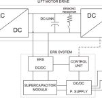
The ERS is connected to the DC bus of the lift motor drive. When an overvoltage in this bus is detected (exceeding approximately 620 V) as a result of the motor starting to work as a generator, the DC/DC power converter extracts that energy and uses it to charge the supercapacitors. In cases where the supercapacitors are fully charged or the converter is limited in power to extract all the energy, the DC bus voltage will continue increasing until the braking resistor starts working. The stored energy is used to feed the ancillary systems through a conventional DC/DC power supply.
The system is composed of four basic elements (Figure 1):
- Unidirectional modular DC/DC converter, connected to the motor drive DC link, uses the braking energy of the lift to charge the supercapacitors.
- Supercapacitors, charged with high power peaks and slowly discharged to feed the auxiliary elements
- DC/DC power supply: a low power converter uses the supercapacitors’ energy to generate the voltage needed by the ancillary systems.
- A solid control unit is necessary for controlling, monitoring and checking the whole system to ensure there are no safety failures under any situation.
2.1. Unidirectional DC/DC Converter
For this system, the converter has to satisfy some essential requirements:
- Be unidirectional: the energy only flows from the DC bus to the supercapacitors.
- Isolated output: the voltage ratio between DC bus and supercapacitors is normally too high to make an efficient converter without a transformer. It could also be recommended for safety reasons.
- High peak power with very low duty cycle, meaning that the converter has to be capable of managing high peaks of power during low periods of time (low average power and low average heat dissipation).
- Lift motor drive compatibility: the converter must be specially designed in a way that the possible disturbances it generates to the motor drive are minimized to avoid unexpected stability, electrical or safety failures.
2.1.1. DC/DC Topology
A modular converter with relatively low power units (up to 2 kW peak) has been selected in order to adjust it as much as possible to a particular lift. With this approach, a quite simple, compact and inexpensive converter can be designed, then paralleled to fit it to demanding power.
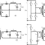
There are several topologies (Figure 2) that can fulfill these characteristics and can be driven directly by standard controllers. The possibility of using this type of controller can reduce both cost of components and development time.
Topologies that are normally used for lower power applications can be adapted if they are carefully designed for this case of high power peak but low average power. For example, two-switch forward or half bridge (resonant or not) are simple and inexpensive topologies normally used for designs below 1 kW that can be used for higher transient power.
2.2. Energy Storage
There are essentially two possibilities for energy storage. The first is supercapacitors, also known as electric double-layer capacitors. These are electrochemical capacitors that have a very high energy density when compared to common capacitors, typically several orders of magnitude greater than a high-capacity electrolytic capacitor.
The second is batteries of two types:
- Lead-acid: these have a much higher energy density than supercapacitors, and their main advantage is that they use old, cheap, safe and very tested technology. They have a large extended use in renewable energies. However, at the same power level as supercapacitors, they are bulky and inefficient.
- Lithium: there are several variants with little different characteristics, depending on the cathode composition. With higher energy and power density than lead-acid, this type of battery is starting to be used in high-power systems. They are expensive and dangerous if used out of their temperature or voltage safe operating areas (SOAs). Therefore, they need an expensive battery-management system to make them work in a SOA.
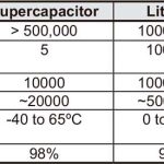
Table 1 shows the main characteristics of the possible storage systems.
Given its pulsed operation, the energy storage system has to satisfy the next main requirements:
- Short time, high peak power demands
- High efficiency
- A very high number of charging and discharging cycles (more than 100 per day)
- High energy density
Based on these characteristics, supercapacitors are the storage system that better fits the present case. Although this technology is relatively new, it has already been tested and used in many other transportation sectors, such as automotive (Schneuwly, et al., 2002) and railways (Steiner, et al., 2007) with good results. Regarding costs, supercapacitors cannot compete with batteries. However, it is interesting to note that supercapacitors can cost around one-fourth the price of power lithium batteries (Burke and Zhao, 2015).
Their major drawback when compared to batteries is their low energy density. This parameter can limit the recovered energy and the maximum time that auxiliary systems can be fed with that energy. Another problem of this storage (which also applies similarly to lithium batteries) is the fact that supercapacitors can only withstand low voltages (typically 2.7 V per cell), so for most applications, they have to be connected in series to get higher working voltages. These capacitors are very sensitive to overvoltage. Hence, once connected in series, balancing electronics have to be used to ensure that no cell surpasses its maximum working voltage.
2.3. DC/DC Power Supply
The power of this converter is typically 50-150 W and usually has to generate several output voltages (12 V, 24 V, 48 V, etc.) depending on the lift ancillary systems’ requirements.
If the supercapacitor working voltage is carefully selected, standard power supplies can be used, avoiding the design of a new power converter, which greatly reduces development costs.
3. Tests on a Real Lift
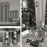
The ERS system has been evaluated in a real lift installation at the ITAINNOVA lift test towers (Figure 3). Energy measurements have been performed according to ISO 25745-1:2015 and 25745-2:2015.
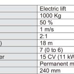
Table 2 shows the main characteristics of tested lift and test tower.
Energy consumption is composed of a running and non-running operation. The running operation energy measurements have been achieved by:
- Running the empty lift car in a closed cycle from floor 0 to 6 and back to floor 0, including the energy used during the two door operations, in accordance with the reference cycle as specified in ISO 25745-1
- Running the empty lift car in a closed cycle from floor 4 to 6 and then back to floor 4, including the energy used during the two door operations, in accordance with the short cycle as specified in ISO 25745-1.
The non-running energy measurements are composed of idle and standby conditions. The idle-condition energy is the energy measured for a period of 1 min., starting immediately after finishing the reference cycle. The standby condition energy is the measured energy maintaining the empty car at the bottom landing for 5 min. after the doors have closed. With these energy values measured, the energy classification for this standard lift can be obtained.
Classification measurements were made first in the “stock” lift without any modifications.
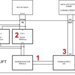
Afterward, the ERS was implemented in the lift for experimental validation (Figure 3). The objective of the measurement was to quantify the amount of energy that can be harvested with ERS on the lift. This allowed evaluating the impact over the energy consumption of the non-running operation and the compatibility of the system with a real lift. Figures 3 and 4 show the three main elements of the ERS: supercapacitor module (1), DC/DC converter connected to the DC Bus (2) and the DC/DC power supply with 24 V to the ancillary elements (3).
The testing process has been performed following the standard indications in a way that the charge level of the energy storage devices is the same at the beginning and the end of each measuring period. This way, the impact of ERS on the energy consumption can be determined. For this reason, the voltage level of the supercapacitor module has been monitored during the whole testing process.
The output of the ERS system has been connected to a variable resistor load (marked as “4” in Figures 3 and 4). Both current and discharge time have been measured in order to quantify the available energy that can be used to feed the non-running operation.
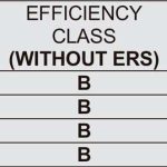
Since in this specific prototype the ancillary equipment is not powered from a single point (i.e., lights are connected directly from AC main), it was necessary to perform a simulation in order to obtain the impact of the ERS contribution on the energy classification of the lift. The lift characteristics are introduced in a quasi-dynamic model for energy-consumption analysis in lifts (Echeverria I, et al., 2014), and the registered energy recovered by ERS is added to supply the standby consumption. Finally, the ISO trajectory (reference cycle and short cycle) and the non-running operation (idle and standby condition) are simulated, and the total consumption of the lift is obtained, producing the results shown in Table 3.
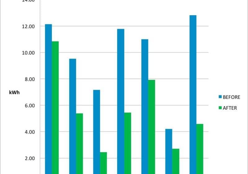
As seen in the results summary of Table 3, the daily consumption is decreased, and a better classification is obtained, showing that a change in class from B to A can be obtained in low-usage categories.
4. Conclusions
The work presented in this paper has produced a new topology of ERS, which is compatible with most of the lifts that allow energy regeneration. This ERS is a patented solution, which has been successfully tested on a real installation with good results in terms of efficiency enhancement.
The modular design allows a plug-and-play connection that facilitates the component connection and makes it easier to fit the solution to the lift, where it is to be implemented. This way, the solution becomes optimal, since the size of the supercapacitor set can be adjusted to the capacity of the lift for energy recovery.
As a result, wasted energy during braking is minimum, and the cost of the supercapacitor storage system is limited to the required one. As the device is based on a one-direction converter, the overall cost is mainly defined by the supercapacitor set, which makes the ERS an economical solution.
Finally, the results obtained on a real lift have shown that lift consumption from the power network can be nearly eliminated during standby operation, which allows to reach a class for lifts where low categories apply, with the corresponding benefits it provides.
Acknowledgement
We would like to thank the technical staff at MP ASCENSORES for their devoted support during the test campaign of this project.
- Figure 1: ERS block diagram
- Figure 2: a) Half bridge b) full bridge c) two-switch forward d) LLC resonant
- Figure 3: Test setup on real scenario
- Figure 4: ERS component topology test
- Table 1: Batteries and supercapacitors comparison table (typical values)
- Table 2: Lift prototype characteristics
- Table 3: Energy efficiency class comparison
References
[1] Tominaga S., Suga, I., Araki, H., Ikejima, H., Kusuma, M., Kobayashi, K., (2002). “Development of Energy-Saving Elevator Using Regenerated Power Storage System”. Proceedings of the Power Conversion Conference, 2002. PCC-Osaka. Vol. 2, pp.890-895, 2002.
[2] Oyarbide E., Jiménez L.A., Molina P., Gálvez R., Bernal C., “Challenges of Low- Voltage Energy Storage for Lifts”, 5th Symposium on Lift & Escalator Technologies, pp. 147-170, 2015.
[3] Li Z., Ruan Y., “A novel energy saving control system for elevator based on supercapacitor bank using fuzzy logic,” 2008 International Conference on Electrical Machines and Systems, vol., no., pp.2717-2722, 17-20 Oct. 2008.
[4] Schneuwly A., Bärtschi M., Hermann V., Sartorelli G., Gallay R., Koetz R., “BOOSTCAP Double-Layer Capacitors for Peak Power Automotive applications”, Second International Advanced Automotive Battery Conference (AABC), Las Vegas, Nevada, 2002.
[5] Steiner M., Klohr M., Pagiela S., “Energy Storage System with UltraCaps on Board of Railway Vehicles”, European Conference on Power Electronics and Applications, Aalborg, Denmark, pp. 1-10, 2007.
[6] Burke A., Zhao H., “Applications of Supercapacitors in Electric and Hybrid Vehicles”, 5th European Symposium on Supercapacitor and Hybrid Solutions (ESSCAP), Brasov, Romania, April 23-25, 2015.
[7] Echeverria I., Arteche F., Iglesias M., Gómez A., Roig J.A., González P., “A Quasi-Dynamic Model for Energy Consumption Analysis in Lifts”, 21st International Congress on Vertical Transportation (ELEVCON 14), 2014.
Get more of Elevator World. Sign up for our free e-newsletter.
