PESSRA in Lifts and Escalators – An Overview
Feb 1, 2019
Basic information intended as a quick guide for lift and escalator field professionals on these important electronic systems that are becoming commonplace
By Lakshmanan Raja and Teck Eng Ng
Electronics are making great headway into the lift and escalator industry, which is now on par with their development in other industries. In our industry, what used to be relay-based hardwired control has been replaced by electronic switches (e.g., transistors), then further enhanced with the introduction of microcontrollers and microprocessors. As a result, the current lift and escalator controller is like a black box, connecting various subsystems together through electrical wiring and electronic interfaces in which the field professionals are able to see only the input and output signals. The operation is well coordinated by built-in programs invisible to the user and maintenance professionals. In recent years, more and more programmable electronic systems (PESes) have been developed and deployed to ensure user safety. Such systems are known as PES in safety related applications (PESSRA). If such devices are used in lifts, the term has “for lifts” added to the end (PESSRAL). If used in escalators, the addition becomes “for escalators” (PESSRAE).
This article presents an overview of PESSRAL/PESSRAE systems, with the coverage on the device architecture, its reliability and information on choosing the right reliability levels. It then discusses the safety functions to be executed by the PESSRA devices and safe states to be achieved. It also includes information on type testing requirements on reliability level verification. Finally, it concludes with the advantages and challenges of using PESSRA.
Inclusion in Code
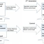
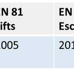
In lift and escalator controllers, electronics devices have traditionally been used only in operation and motion control, with the safety- related controls hardwired and relay controlled. In recent times, we can see the electronic influence expanded into the processing of input from safety-related devices. In such control, the classic hardwired logic is transformed to a functional- based control. The functional requirements are more outcomes based, and its implementation is open with different hardware and software architecture in a variety of ways. The developmental phases of lift and escalator controllers is presented in Figure 1. As more and more lift and escalator manufacturers used PESSRA devices in their controller, the code came to include the requirements for them. The official inclusion dates of PESSRA in the U.S. and European codes are given in Table 1.
Device Architecture
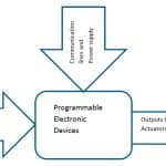
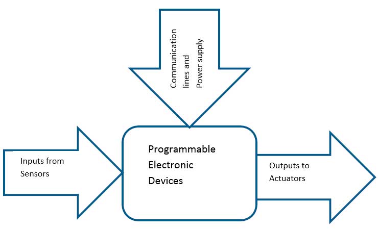
The generic architecture of a PESSRA controller is shown in Figure 2. It consists of input sensors, programmable electronic device and an output actuator. There is no direct hardwired connection between the safety signals on the input side and output side. The input signals are processed by the programmable electronic devices, which then control the actuator on the output side. Examples of programmable electronic devices are: microprocessors/microcontrollers, programmable logic controllers, field- programmable gate arrays, application-specific integrated circuits and other computer-based devices (smart sensors, transmitters and actuators).
Safety Integrity Level (SIL)
The reliability of the safety device is always very important. When the electronics system with hardware and software is used to make decisions related to user safety, its reliability is measured with SIL. SIL is a numerical reliability measure or indicative failure rate of the PESSRA system that executes the safety function.
Two types of safety functions exist: “high demand mode” or “continuous mode” (probability of failures per hour), and “low demand mode” (probability of failure per annum). With reference to IEC 61508-4 Clause 3.5.16, the high-demand definition is called for when the demand on a safety-related function is greater than once per annum and the low-demand definition when it is less frequent. The key characteristics of a high-demand-mode safety function are:
- It generally provides some control function during normal operation.
- Failure of the safety function usually leads to a hazardous situation.
- The frequency of demands placed upon it are high, more than once per year or even continuous.
Example: Traction Machine Normal Brakes
The key characteristics of a low-demand mode safety function are:
- It is generally not used during normal operation.
- Failure of the safety function results in loss of protection but is not, in itself, hazardous.
- The frequency of demands placed upon it is low, less than once per year.
Example: Safety Gear
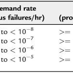
Most PESSRA devices used in lifts and escalators belong to the second category of demand-mode safety function type. The probabilities of failure on demand for low-demand-rate functions are given in Table 2, which is from IEC 61508-1. The SIL 4 controllers are very highly reliable, since their failure on demand is very low, ranging from 10-5 to 10-4. SIL 1 is the lowest, and its failure on demand ranges from 10-2 to 10-1. SIL 3 is the highest level used for the lift and escalator industry.[3]
The following example gives an idea on the SIL and its failure rate: The emergency-stop switch requires SIL 3 per EN 81-20 and ASME A17.1. So, its acceptable failure rate should be between 10-4 and 10-3. If we assume that the demand is once a year, it is acceptable to fail once between 1,000 and 10,000 years.
Deciding the SIL Rating
Now we know the SIL, but how do we decide which level might be suitable for a particular safety function? We can decide that with three steps:
- Hazard occurrence frequency should be calculated based on the risk analysis.
- Compare the occurrence rate with the tolerable rate (from R2P2[a] or any other acceptable standard).
- The difference (i.e., the gap) should be filled with the appropriate PESSRA SIL (reliability level)
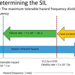
The following example will explain the above: assume that the lift undergoes an uncontrolled movement once in five years. The hazard occurrence frequency (#1) is 1/5 year, which is equal to 0.2/year. Whenever the uncontrolled movement happens, the probability of a fatal incident happening (#2) is 0.01. The probability of a fatal incident rate for our system is the product of #1 and #2: 0.2/year X 0.01/year = 2 X 10⁻³/year (two fatal incidents in 1,000 years). However, the tolerable fatal rate for the public generally used in functional safety is 10-5/year. [8]
Here, there is a gap between the tolerable and the actual rates. The PESSRA controller used to bridge the gap must satisfy:
Failure rate = tolerable rate/actual rate = 10-5/(2 X 10-3) = 5 X 10⁻³ SIL 2 controllers have a failure rate between 10-3 and 10-2. These controllers will be able to meet our required failure rate of 5 x 10⁻³. Figure 3 helps show the calculation process.
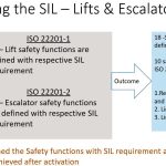
However, for lifts and escalators, the SILs for the various safety functions have been decided by the codes developed by the industry (Figure 4). There are 51 safety functions defined for lifts with respective SIL rating in ISO 22201-1. In the same way, there are 26 safety functions defined for escalators with respective SIL rating in ISO 22201-2. In addition, the code also defined the safety state, which needs to be achieved by the PESSRA controller whenever a demand is placed on the safety function. There are 18 and 10 safe states defined for lifts and escalators in ISO 22201-1/-2. Examples of safe states are: removing power from the traction machine, limiting the travel range and speed, etc.
SIL Verification
Since the reliability of the PESSRA system depends on the SIL, its verification is very important. It is performed by an approved body, which is the laboratory that undertakes both the testing and the certification. It is either a manufacturer operating a full quality-assurance system defined and approved by a national authority, or a certified third party accredited by a national authority for the scope of lifts, escalators, moving walks and corresponding safety devices.
The application for type examination shall be made by the manufacturer of the component or the manufacturer’s authorized representative and shall be addressed to an approved test laboratory.
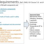
For doing SIL verification and type testing, the approved body requires two printed circuit boards: one bare and with full components on it and the other with details like layout and input/ output definition if the safety circuit only has electronic components. For PESSRA, details on software, a functional description (including software architecture and hardware/ software interaction), description of data, variables and interfaces, etc., must be provided. For more details, refer to EN 81-50, clause 5.6 and Annex B.
The approved body will do the needed mechanical tests like vibration, bumping and temperature tests, and a functional test on software coding and design.
Maintenance and Repair
Since PESSRA controllers deal with the safety, their maintenance and repair is very important. The manufacturer shall provide the instruction manual, which contains information about carrying out the functional verification test and:
- Identification, labeling and certification details of PESSRA components
- Assembly, connection, adjustment and training details
- Frequency of functional verification
Concerning the maintenance and repair of a PESSRA device, the instruction manual shall provide the details on the following:
- Proof test, and preventive and breakdown maintenance activities to be carried out
- Unique maintenance measures and techniques
- Time interval of maintenance activities
- Test equipment used; activities for fault diagnosis and repair
- Activities for revalidation
- Maintenance and failure reporting requirement
Advantages and Challenges
As the lift and escalator control advances, there will be more application of PESSRA systems. The advantages of PESSRA over the hardwired control are:
- The PESSRA devices have programmable intelligent components capable of self-monitoring and early detection of failure. This capability provides early warnings on the possible system faults, which will lead to better system reliability.
- The PESSRA devices are connected through communication bus, so bypassing an individual device should be done through software means. Thus, unauthorized bypassing and tampering of safety features by jumper cables can be avoided. In addition, space savings can be achieved through less wiring.
- PESSRA is an electronic device, so the operation voltages will be low; thus, electric shock can be avoided.
However, the advantages come with certain challenges, like:
- The PESSRA control involves both hardware and software design, so it will be very proprietary, with the OEM having an edge over third parties.
- Skilled personnel in both hardware and software are needed to design, test and verify system operation.
Conclusion
This article provides the basic information and a quick guide on PESSRA for the lift and escalator field professional. For deeper knowledge, see “References.”
- Figure 1: Lift and escalator controller development
- Figure 2: Architecture of a PESSRA device
- Figure 3: Determination of SIL
- Figure 4: Safety functions, SIL and safe states[3 & 4]
- Figure 5: Type testing process
- Table 2: Different SILs and their failure rates[6]
- Table 1: Date of PESSRA inclusion
References
[1] EN 81-20:2014 Safety Rules for the Construction and Installation of Lifts — Lifts for the Transport of Persons and Goods Part 20: Passenger and Goods Passenger Lifts.
[2] EN 81-50:2014 Safety Rules for the Construction and Installation of Lifts — Examinations and Tests Part 50: Design Rules, Calculations, Examinations and Tests of Lift Components.
[3] ISO 22201:2009 Lifts (Elevators) — Design and Development of Programmable Electronic Systems in Safety-Related Applications for Lifts (PESSRAL).
[4] ISO 22201-2:2013 Lifts (Elevators), Escalators and Moving Walks — Programmable Electronic Systems in Safety Related Applications Part 2: Escalators and Moving Walks (PESSRAE).
[5] ISO/TR 22201-3:2013 Lifts (Elevators), Escalators and Moving Walks
— Programmable Electronic Systems in Safety Related Applications Part 3: Life Cycle Guideline for Programmable Electronic Systems Related to PESSRAL and PESSRAE.
[6] EN 61508-1:2010 Functional Safety of Electrical/Electronic/Programmable Electronic Safety-Related Systems Part 1: General Requirements.
[7] EN 61508-4:2010 Functional Safety of Electrical/Electronic/Programmable Electronic Safety Related Systems Part 4: Definitions and Abbreviations.
[8] Smith, David J., and Kenneth G.L. Simpson. Safety Critical Systems Handbook: A Straight Forward Guide to Functional Safety, IEC 61508 (2010 Ed.) and Related Standards, Including Process IEC 61511 and Machinery IEC 62061 and ISO 13849 (Elsevier, 2010).
[9] HSE, Reducing Risks. “Protecting People.” HSE’s Decision Making Process. Crown, London (2001).
Get more of Elevator World. Sign up for our free e-newsletter.
