Plenty of Room
May 1, 2018
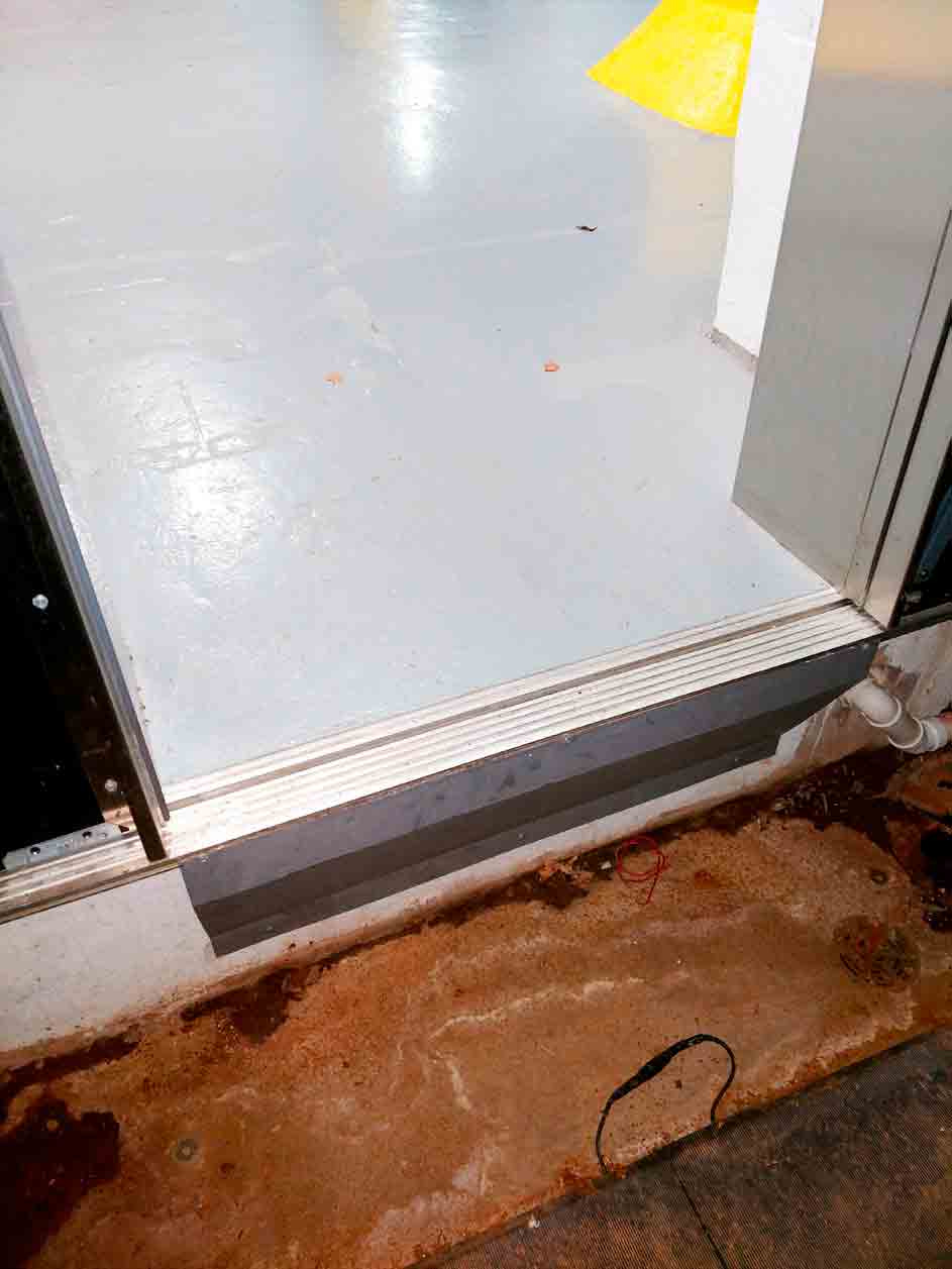
Gillespie solution puts shallow-pit modernization of traction elevator in compliance with code.
When field conditions do not allow for sufficient pit depth or overhead to provide the vertical clearances required by the ASME A17.1 Safety Code for Elevators and Escalators, Gillespie Corp. has a solution. With the introduction of the Americans with Disabilities Act (ADA), Gillespie began receiving an increasing number of calls to design a safety system that would mechanically and automatically provide refuge space for tight conditions, both above and below the elevator. Some situations only involve insufficient pit depth, others only low overhead conditions, and still others are challenged with both a shallow pit depth and low overhead.
Typically, we see this need in older buildings with existing structure or in new construction taking place under unfavorable conditions. Often, structural elements — footings or structural beams, for example — make it impossible to provide a pit or sufficient overhead. Often, an elevator is required to be located above occupied space, below occupied space or both. Obviously, in these situations, pit depth and overhead often can be limited. Less frequently, local building codes will not allow for the addition of a “doghouse” at the roof level that would allow for minimal overhead.
Gillespie designed and patented both its Shallow Pit Safety System and Low Overhead Safety System to meet these needs. These safety systems incorporate automatic, power-operated mechanical devices that, when deployed, stop the motion of the elevator, providing the refuge space required by code. The safety systems are activated from outside the shaft for maintenance and inspection, but, should someone gain access to the shaft without operating the safety systems — either below or above the elevator — secondary backup detection will automatically deploy the safeties and take the elevator out of normal operation. In the case of the shallow-pit safety system, this operation can take place even during a power outage.
In addition to the safety systems, Gillespie developed telescoping car aprons that allow for shallow pit depth and provide the front vertical surface height required by elevator code. The telescoping car apron is only allowed to collapse while the elevator approaches the lower landing from above. The apron must be fully extended when the elevator is above the lower landing. Operation of the elevator above the lower landing with the car apron even partially collapsed is prevented.
The Challenge
Elevator Maintenance of Buffalo was contracted to modernize an elevator in the Larkin Center of Commerce at 701 Seneca Street in Buffalo, New York. The contract called for a new traction elevator in a space with sufficient overhead but shallow pit depth. Prior to the project, called Elevator 14, Gillespie used its safety systems for projects involving directly coupled or roped holeless hydraulic elevators, but for this one, we proposed incorporating our shallow pit safety system and telescoping car apron with traction-elevator technology.
The elevator originally had been installed in the early 1900s, and the time had come to replace all the equipment. At the same time, there was a need for the elevator to have a landing at the basement level, one floor below the current lowermost floor. Previously, the basement had been used as a walk-in pit. When the pit floor slab was excavated, it was found that further digging for a conventional pit would compromise the integrity of the building structure. The maximum pit depth possible was 1.5 ft.
Elevator 14 had an existing overhead machine room and a shaft nearly 100 ft. high. Since only the lower five floors were scheduled for access, the available overhead was 36 ft. Overhead clearance was obviously not the problem; the shallow pit was what presented the challenge.
Traction elevators require more runby and overtravel than hydraulic elevators, and choosing the correct type of buffer was key to adapting the Gillespie Shallow Pit Safety System for a traction-elevator application.
A normal traction elevator with a standard pit depth would have Type A or Type B safeties below the bolster planks underneath the platform, with roller guides mounted below the safeties. The shallow pit depth did not allow for this arrangement.
The Solution
Gillespie reviewed the constraints and determined that a traction passenger elevator could be designed to meet the conditions. The Shallow Pit Safety System and telescoping car apron were adjusted to meet the higher car speed encountered. The telescoping car apron was redesigned for a vertical face height of 48 in., as mandated for elevators complying with the requirement for unintended car movement.
To meet the requirements of fitting car safeties and roller guides within the constraints of the shallow pit depth, it was necessary to get inventive. The platform was designed with the strength of the bolster planks built right in, allowing the platform to come level with the lower landing, while still complying with code for both runby and buffer spring stroke.
Design and Production
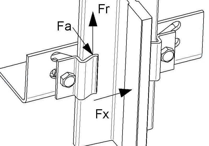
The elevator provided has a 6-ft.-X-6-ft., 5.5-in. platform. The travel is 60 ft., 11 in.; the capacity is 2500 lb. at a speed of 100 fpm. Both the elevator and counterweight are guided by two 15 lb.-ft. T-rails connected to the existing structural masonry wall with brackets. There is 36 ft. of overhead clearance. The machine is a Hollister-Whitney #43 with a 10-hp motor, located in the overhead machine room.
The cab and entrances were purchased from Minnesota Elevator and are standard wood-core, plastic-laminate walls; stainless-steel front end; and stainless-steel single speed, center-opening entrances. A GAL MOVFR door operator with a Tritronics sensor screen was employed. The car and hall fixtures were from Innovation Industries, with stainless-steel faceplates in their Bruiser series. The controller was designed and built for Gillespie by Motion Control Engineering.
The Shallow Pit Safety System uses steel pedestals mounted to the walls on either side of the elevator and deployed and retracted by electric actuators. The system is supplied with battery backup, allowing it to function even in the event of a power failure. Industrial shock absorbers are mounted to and built into the car frame. These attenuate the energy of the elevator striking the safety pedestals. It is possible to test the system repeatedly, fully loaded and at full down speed, without damage to the elevator.
The elevator car frame is specifically designed for the shallow pit depth and to work with the safety pedestals. This is as important to the success of the design as are the safety pedestals and controller.
Operation
To access the pit area, it is necessary to put the car into access-enable mode at the car station, open the car and hall door, and raise the car using the access key until the lower access limit switch stops the elevator at a good working height. The safety pedestals automatically deploy, allowing safe access to the pit area. If the access key is not used, and the doors are opened with the elevator parked at an upper landing, the act of stepping down into the pit will trigger the safety system to deploy through detection. It is physically impossible for the elevator to come down into the pit when the safety pedestals are deployed.
To place the elevator back into service, simply exit the pit, and, with the door held open, lower the car on access until the doors are engaged. The safety pedestals automatically retract out of the way as the elevator is lowered.
Conclusion
The first elevator with the Gillespie Shallow Pit Safety System was installed in 1991. Before the Elevator 14 traction-elevator project, the focus was on hydraulic and roped-hydraulic elevators utilizing the Shallow Pit Safety System, the Low Overhead Safety System, or both for the same elevator. With the successful Elevator 14 project, Gillespie demonstrated it can now provide traction elevators limited to a shallow pit depth with a safety system that meets code.
Get more of Elevator World. Sign up for our free e-newsletter.

