Rationale for Developing a Brake Tester
Jun 1, 2020
How addressing an accident and preventing future similar ones resulted in a generic brake monitor.
by Dr. Albert So, Dr. K.H. Lam and Chung To “Andy” Kong
This article was first presented at the 2019 International Elevator and Escalator Symposium in Las Vegas.
In May 2018, a fatal accident related to the failure of an elevator brake occurred in Hong Kong. The victim waited at the seventh floor for the elevator, which was traveling upward from the ground floor. Owing to various causes, the two brakes were unable to fully stop and hold the elevator car stationary. When the doors were opened at the seventh floor and the victim got into the elevator car, it continued to move upward. The victim was then trapped between the landing lintel and the car door sill.
The victim managed to escape being trapped but then fell into the pit and was killed. Owing to this accident, the brake system of all similar models of the same brand was thoroughly inspected as required by the legislation enforcement authority.
To address the causes of the accident and develop a means to prevent similar accidents, the University of Hong Kong began to design a generic brake monitor to ensure the proper operation of a standard elevator brake and trace its trend of deterioration. The occurrence of the accident, causes of the brake failure and relevant clauses regarding brake requirement in the safety code of practice of Hong Kong were first introduced at the 2019 IEES.
Various features of the device to closely monitor the brake solenoids, springs, brake arms, brake pads and working performance of the brakes will be discussed. The design is generic enough to be applicable to most standard installations in Hong Kong. These features have been particularly designed to tackle the various causes of the accident, which are also common problems that have led to unintended car movement (UCM) in recent years. The electronics and information technology to be employed to upload useful raw and processed data to the cloud for accident investigation, just in case, will also be described. Algorithms to process raw data will also be highlighted.
The Fatal Accident — Rationale to Develop the Brake Monitor
The description of the accident, as follows, is based on the Technical Investigation Report on Lift Incident at Paris Court prepared by the Electrical & Mechanical Services Department (EMSD) of the Hong Kong Special Administrative Region (HKSAR) Government.[2] At noon on May 11, 2018, a fatal accident happened at a high-rise residential building in Hong Kong. A vacant elevator traveled up from the ground floor to the seventh floor in response to a landing call from there. At the seventh floor, the landing and car doors opened, and the victim, an older woman, entered the car, but it continued to move upward with both doors still open. The victim was trapped between the landing lintel and the car door sill. She attempted to escape but fell down to the elevator pit and was killed. Finally, the elevator stopped at about the 12th floor.
The lift was an electric elevator with a rated capacity of 1000 kg and a rated speed of 1.75 m/s, a 1:1 roping arrangement and with a worm gear. The brake was of the old type; i.e., a single compression spring. The date of the elevator’s last annual examination was March 2, 2018, while its last routine maintenance was carried out on May 9, 2018. A full investigation and onsite testing were conducted by EMSD after the accident, and some findings were discussed as follows.
Based on the closed-circuit TV (CCTV) footage, the elevator moved upward unintentionally four times during the same morning before the accident. Since there was no injury, the problem did not draw attention, and the management company had not been aware of a problem. As mentioned before, after the victim entered the elevator, it continued to move upward with both doors open and finally stopped at the 12th floor.
During the investigation, a post-accident simulation in which the elevator was instructed to adopt the same travel pattern as recorded by the CCTV right before the accident was carried out. A thermal imager was used to measure the temperature of the brake solenoid and the brake linings or pads. After half an hour elapsed, the brake plungers started to operate asynchronously and sluggishly, with a delay around 1 s long. At 70 min after the commencement of the simulation, the brake plungers failed to move, meaning neither brake arm could be opened anymore. Since the brake could not be opened, the two brake linings were resting on the rotating brake drum. Then, the temperature of the two linings started to rise to a steady value of around 220°C. At three-and-a-half hours after the commencement of the simulation, the elevator moved while the landing doors were still open; i.e., a situation of UCM.
After the simulation, the braking system was dismantled, and it was found that the plunger housing had not been lubricated for a long time, as dried lubricant was found on the inner surface. On one lining, the head of one screw, out of 10, was seriously worn by about 3 mm, while another screw was missing. The screws on the other lining were found intact and normal. Two obvious scratches corresponding to the positions of the two abnormal screws were found on the brake drum. An experiment was later performed to measure the coefficient of friction (COF) of such lining, as compared with that of a new one. It was found the COF dropped by about 40%. A compression test of brake linings was also carried out afterward, revealing that the vertical force to maintain a constant compression, say, 0.5 mm, of an overtemperature lining, was much less than that of a normal brake lining, around 1 to 5.
The report concluded that the accident was caused by jamming of the brake plunger, which was not properly lubricated inside the solenoid housing. This led to an incomplete opening of the brake arms while the elevator was moving, resulting in an overtemperature situation with the brake linings, as they were not fully separated from the brake drum. The continuous partial contact between the brake lining and drum produced vibration that loosened the fixing screws of the linings. As the screws protruded outward from the lining, scratches were produced on the drum, further reducing the contact area between the lining and drum. As a result, there was insufficient braking force to hold the elevator when it stopped at the seventh floor to answer the landing call of the victim. Since there was only one passenger inside the car during the accident, the counterweight side was much heavier, and, therefore, the elevator continued to move upward.
Because of this accident, the authority paid much higher attention to brake safety and considered that more measures may be necessary to monitor brake performance. The Department of Electrical and Electronic Engineering of the University of Hong Kong was asked to look into the development of a brake tester to keep track of brake performance 24/7. Before we look at the development, it is appropriate to first review the statutory codes related to brakes in Hong Kong.
Safety Code Enforced in Hong Kong
In the last century, Hong Kong had been adopting the British Standards (BS) on technical requirements for elevator safety, BS 2655, then BS 5655 and, finally, EN 81 in the 1980s. In 1993, EMSD published the first local safety code, Code of Practice on the Design and Construction of Lifts and Escalators,[1] which was revised in 2000 and 2010. In 2018, EMSD started to consider full adoption of the new European versions EN 81-20 and -50. According to the statutory code, a modern elevator brake must perform as follows:
- Able to stop the machine when the car is traveling downward at rated speed and 125% load.
- Average retardation of the car shall not exceed 9.81 m/s2 and be at least 1.96 m/s2.
- Each of the two sets of brakes can perform independently.
- Any one set can independently brake the elevator at rated speed and 100% load downward, or at rated speed and 0%load upward.
- Braking shall become effective without supplementary delay after opening the brake-release circuit.
- Operation of an overload and/or overcurrent protective device for the brake shall initiate the simultaneous de-energization of the machine.
- Current shall not be applied to the brake until the motor has been powered.
Except for items 6 and 7, the monitor shall be able to check relevant parameters to confirm the healthy operation of the brake.
Parameters to Be Measured
The following parameters are continuously monitored by the hardware structure (which will be discussed in the next section). First, the DC current of the brake solenoid is to be measured, because any change of it may indicate something wrong with the solenoid. It is usually measured by the use of a Hall effect current transducer, because ordinary current transformers are not applicable to DC circuits.
Second, the motion of each brake arm is to be measured to check whether the operation of the brake arm is synchronous with the on/off condition of the solenoid current. Furthermore, the motion of each arm also indicates if the spring acting on the arm has deteriorated. Two accelerometers are used, one close to the top of the arm and one close to the bottom, to check whether there is any external obstacle between the drum and arm.
Third, the temperature of the brake lining is to be monitored, because a continuous partial contact between the lining and drum during operation of the motor certainly increases the temperature, as mentioned in the report of the accident. It may technically be a bit difficult to directly measure the temperature of the lining, but it is much easier to measure the metallic part of the brake arm. There is no means to precisely measure the temperature, though an overtemperature alarm may be good enough.
Fourth, a new brake lining is rather thick. But, if the drum rotates from time to time when the lining is in partial contact with it, the thickness is gradually reduced, like the situation of a vehicle brake. It is meaningful to measure the thickness of the lining, but the accuracy may not be that high, because we are just talking about a reduction of a couple of millimeters.
Fifth, the instantaneous position, speed, direction of travel, acceleration and deceleration of the elevator car are to be monitored as a good reference for comparing the performance of the elevator system with other parameters under monitoring.
Sixth, the acceleration and deceleration of the elevator car are to be monitored continuously. Crosschecking such value with values of other parameters can give us more information about the health of the whole system. Note, the hoist ropes are elastic, and slippage between ropes and grooves on the drive sheave is unavoidable. It is useful to measure the motion of the elevator car directly.
Finally, various clean contacts to indicate the status of the elevator system are to be monitored (as discussed in the next section).
Hardware Structure of the Brake Monitor
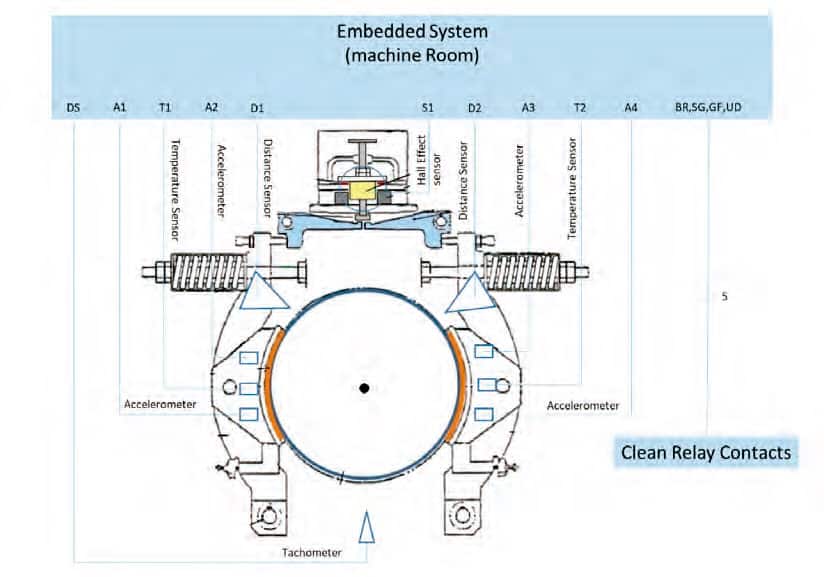
Figures 1 and 2 show the placement of sensors of the brake monitor in the vicinity of the brake. As seen from
the illustration, this is an old version of the brake, as evidenced by the fact there is only one independent solenoid. This design is the same as that involved in the accident. It is easy to add one more Hall effect current transformer to tackle modern brake design with two independent solenoids. The tachometer is attached to one end of the axle of the drive motor so that the real-time speed and position of the elevator car are estimated by calculation.
According to the design requirements, the monitor must not interfere with the normal operation of the elevator, nor downgrade any safety standard according to the statutory code. Five relays that draw signal from the controller are to be provided by the maintenance contractor. Relay 1 indicates the status of the brake solenoid; relay 2 indicates the status of the speed governor; relay 3 indicates the elevator car is at the lowest position; relay 4 indicates whether the car is stationary or in motion; and relay 5 indicates the direction of the car’s movement.
Two accelerometers are installed on the car top, one on the right and one on the left. The embedded computer on the car top continues to communicate with the one inside the machine room, (Figure 1) through a Wi-Fi signal. The use of Wi-Fi is good enough, because the maximum distance between the car top and machine room is only a couple of hundred meters, and there is no blockage in the shaft between the two.
By checking the exact time when current is injected into or removed from the solenoid, and the exact time when each brake arm starts to move, we are able to tell whether the operation of the brake is on time. The duration of travel of the brake arm can also tell us if the spring or solenoid is healthy. It is expected that, when there is some fatigue with the spring or there is some short-circuit within the solenoid, the brake arm tends to operate a bit slower. By keeping track of the temperature of the brake arm, we can tell whether there is partial contact between the brake lining and brake drum when it is rotating. By measuring the distance between a certain point of the brake arm from the surface of the drum, we may be able to judge if the thickness of the brake lining is reduced due to aging, and whether the balance of the force between the solenoid and spring varies slightly. By checking the tachometer, we can tell if the elevator car is moving. Finally, by using the two accelerometers on the car top to check the exact time when there is any current change in the brake solenoid and the time when the elevator car starts to decelerate, we are able to tell whether the elevator car’s deceleration rate is in accordance with the statutory requirement. By integrating the data from the two car-top accelerometers, we can roughly estimate the distance traveled during emergency braking. (The tachometer can also give some hints on this performance.)
Software Structure of the Brake Monitor
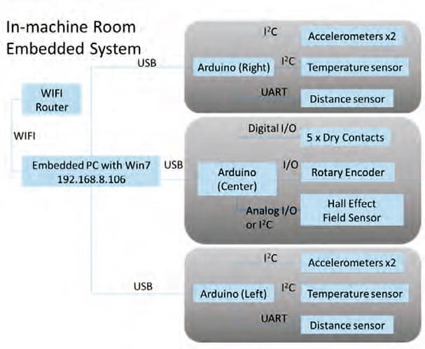
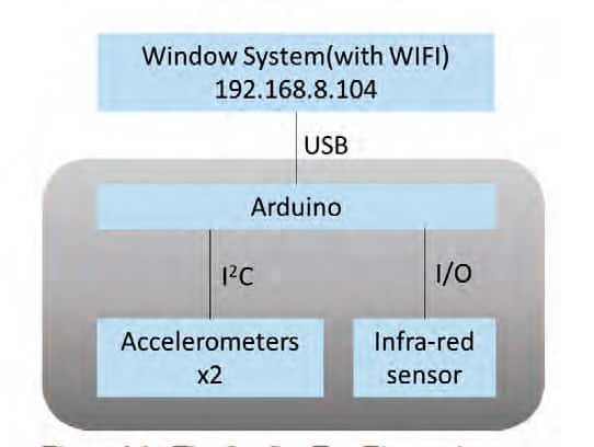
Figure 2 shows an electronic system in which there are three Arduino boards, each connected to a few sensors via either I2C ports or input/output (I/O) ports. These three boards are hardwired to the embedded PC inside the machine room, which continuously communicates with another embedded PC on the car top. Windows 7 has been used as the operating system, but it was planned to soon be upgraded to Windows 10. Figure 3 shows the on-car-top electronic system.
Similarly, an Arduino board is used to retrieve signals from the two accelerometers. This board is hardwired to the embedded PC on the car top, which continuously communicates with the one inside the machine room.
Some Preliminary Raw Data
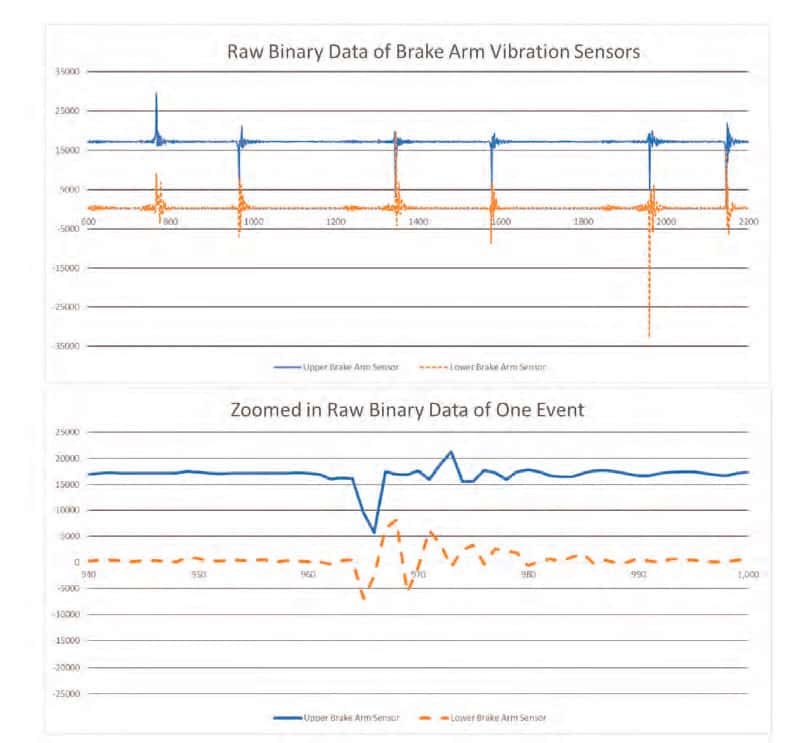
Inside the machine room, the brake-arm vibration sensors could be considered the major devices of the whole system, as they monitor the normal and abnormal operation of both arms. It is possible to detect problems with the operation of each side of the braking system by checking the vibration profiles. Figure 4 shows the raw data of three cycles of “opened-closed” operations of the brake. The sampling rate was 200 Hz, revealing that each operation lasted only around 20 data points; i.e., 20 X (1/200) s = 0.1 s — a really quick operation. The zoomed view showed a “closed” operation of the first cycle. The research team is looking into the details of the waveforms to evaluate data being revealed. On the car top, we have the following data format of all sensors, including the timestamp from the Arduino, the three-axis vibrations of the two accelerometers (“L” for “left” and “R” for “right”), the IR sensor, and the real time as added by the main computer:
(Time_Stamp, AcXL, AcYL, AcZL, AcXR, AcYR, AcZR,
IR, RealTime):
(3205675876, -15536, -244, -4380, -8488, -13280, -3520, 1,
‘2019-09-03 00:16:43.626’).
Conclusion
Owing to the occurrence of a recent fatal accident in Hong Kong, the authority of statutory regulations of the HKSAR Government intended to upgrade the brake monitoring procedures to avoid further accidents. To address and even predict failures with the braking system that led and could lead to similar accidents, a research team at the University of Hong Kong was formed to develop an online brake monitor, the features and structure of which have been highlighted in this article. Some preliminary raw data has also been included. This project is still ongoing, and more results will be available by the time of the symposium.
Acknowledgement
This project is still ongoing and financially supported by the EMSD of the HKSAR Government. More results will be published in a future edition of ELEVATOR WORLD.
References
[1] EMSD. Code of Practice on the Design and Construction of Lifts and Escalators (1993).
[2] EMSD. Technical Investigation Report on Lift Incident at Paris Court, Sheung Shui Town Centre, New Territories (2018)
Get more of Elevator World. Sign up for our free e-newsletter.
