Remote Monitoring and Supervision System
Nov 1, 2012
A system to control hundreds of lifts over TCP/IP network is presented and detailed.
André Guerra, Rui Pinheiro and António Garrido
This paper was presented at  USA 2012, the International Congress on Vertical Transportation Technologies and first published in IAEE book Elevator Technology 19, edited by A. Lustig. It is a reprint with permission from the International Association of Elevator Engineers
  (website: www.elevcon.com). This paper is an exact reprint and has not been edited by ELEVATOR WORLD.
Key Words: Remote control, monitoring, maintenance control, data acquisition, assisted maintenance
Abstract
The Portuguese railway company owns over 400 lifting equipment, including lifts, escalators and conveyors, representing over 20 different models from different manufacturers. It was identified the need to control the status of these equipment (events, alarms, cumulative information, etc.) as well as the performance of the maintenance company. The goal is to implement a system that, based on the collected information, allows an overtime analysis of several parameters, concerning the lifting equipment itself and the action of maintenance personnel.
In this context, it is presented a system that was developed to comply with these needs. It is composed of an acquisition part – collects information from equipment, a processing unit – processes information and places it over a TCP/IP network, and software – for visualization of the information and reports.
1. Introduction
The purpose of the system described in this paper is to perform remote monitoring of lifts, escalators and conveyors, located in the stations and other infrastructure of the Portuguese railway company (REFER).
The Portuguese railway company felt the need to control the status of its equipment to improve the effectiveness of exploitation activities and to support their maintenance, reducing costs and improving customer service.
This system also had to be integrated on the Technical Supervision System (SCADA) currently existing in REFER.
The goals of the system are, among others:
- Real time monitoring of the equipment.
- Available statistical data of the equipment regarded to their availability, maintenance requirements, etc.
- Indicators of the performance of the maintenance company, such as regularity of interventions, time to respond to situations of failure, intervention time for both preventive or corrective maintenance, etc.
- Perform some remote commands, such as putting the equipment out of service when it is not needed.
2. Main Body
2.1 System Description
The system consists of an interface that collects information from the equipment and sends commands to it; a processing unit (Programmable Logic Controller) that processes the information and places it over a TCP/IP network; and software to integrate the solution with the SCADA for visualization of information and reports.
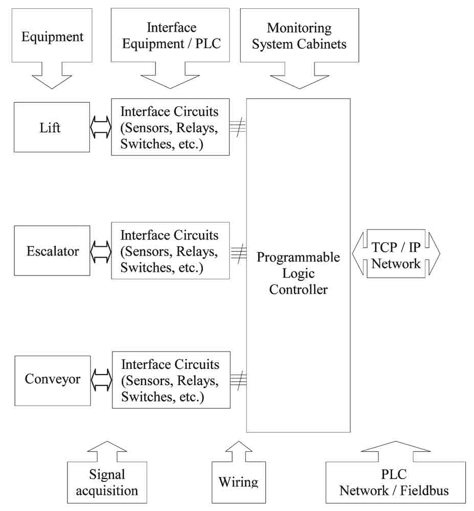
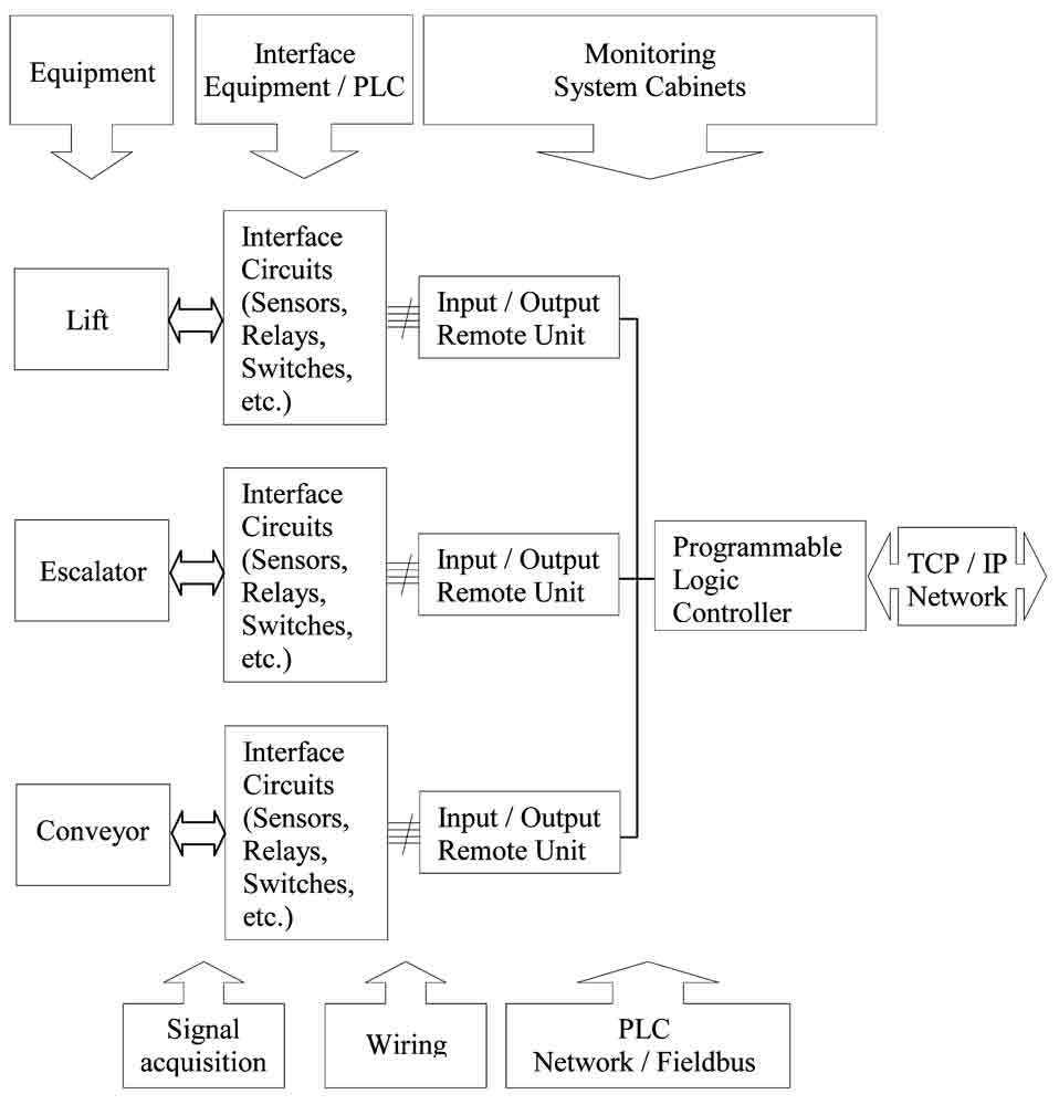
There are two types of configurations: one where the Programmable Logic Controller (PLC) makes direct acquisition of the signals and another one where the acquisition is made using several remote input / output units that connect to a Programmable Logic Controller though a fieldbus network.
These configurations are indicated in the following diagrams:
In this configuration the PLC makes the direct acquisition of the equipment signals and connects to the REFER network. Each PLC supervises one or more equipment.
In this configuration there are remote I/O units that acquire the information and connect to the PLC by means of a fieldbus network.
Equipment:
Generally called equipment, the lifts, escalators or conveyors can be one or several, per station, and placed apart, in some cases, hundreds of meters.
Interface equipment / PLC:
The system was projected to provide a complete independence between the monitoring system and the equipment so that doubts could never be raised by the manufacturer of the equipment about eventual interferences or questions regarding the equipment’s certification. So the signal acquisition is done using external devices such as magnetic sensors, limit switches, auxiliary contacts, voltage detectors, temperature sensors, etc.
2.2 Signals and Interface
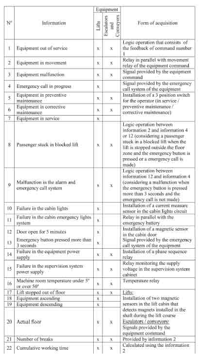
For each type of equipment (lift, escalator or conveyor) it was identified a list of signals to acquire and commands to send.
On the following table it is described the list of signals/commands and the way they are acquired.
In the following tables the list of information and commands is presented, as well
2.3 Programmable Logic Controllers and Communication Protocols
To process the signals and the commands for each equipment there is at least one PLC per location. The PLC does all the processing and communicates with the SCADA existent in the Technical Supervision System for Infrastructure currently existing in REFER.
The protocol used to communicate with the SCADA is Modbus / TCP.
The physical infrastructure for the communication is a fiber optic TCP/IP network that connects all the Portuguese railway stations and infrastructures but the PLCs are also prepared to use GSM/GPRS communication.
The PLCs have a modular architecture and have a second communication port for fieldbus network, using the Modbus protocol to communicate with remote I/O modules.
2.4 Technical Supervision System
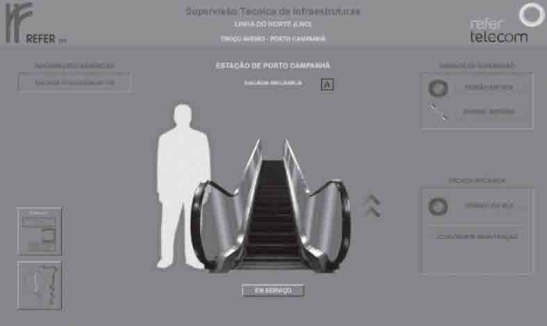
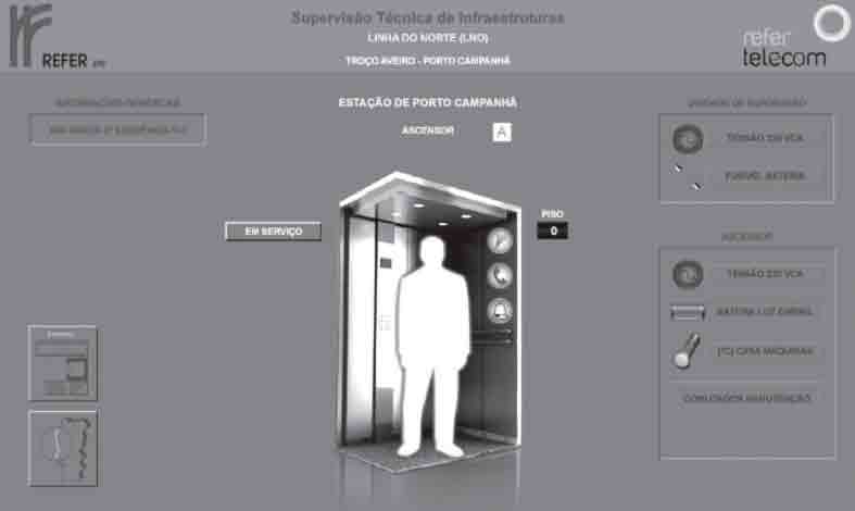
It was developed a user interface to integrate the existing technical supervision system of the REFER infrastructures. This interface allows a real time monitoring of all the equipment as well as the generation of reports.
3. Results
The system has worked as expected and the integration with the Technical Supervision System for Infrastructure was possible.
The achievements obtained were:
- Real-time monitoring of the equipment.
- On-line statistical information of the equipment regarding to its availability, use, failures and others.
- Better and fast response in case of equipment failure.
- Possibility to monitor and analyze the performance of the equipment maintenance company.
- After six months of exploitation, it was noticed an improvement in the equipment’s availability indexes as a result of a fast response by the maintenance company and the ability to prevent malfunctions by means of analyzing the statistical data.
4. Conclusions
During this project it was possible to create a manufacturer independent system that can be used in any lifting equipment, both for monitoring signals and sending commands.
All the data managed by this system was exchanged by a Modbus over TCP/IP, allowing the integration with a third part SCADA system.
The implementation of the system produced the expected results, allowing the proprietary of a network of more than 400 lifting units, the full control of their equipment, not only in terms of real times status, but also in terms of overtime information.
Finally, 6 months after the startup of the system it was possible to gather important information about the equipment, resulting in better maintenance that led to a better performance.
Get more of Elevator World. Sign up for our free e-newsletter.
