Risk Potential of Safety Gears
Mar 1, 2015

This paper was presented at  Paris 2014, the International Congress on Vertical Transportation Technologies, and first published in IAEE book Elevator Technology 20, edited by A. Lustig. It is a reprint with permission from the International Association of Elevator Engineers
  (website: www.elevcon.com). This paper is an exact reprint and has not been edited by ELEVATOR WORLD.
Abstract
It is a preferred practice all over the world to test the safety gear with weights when elevator systems are placed on the market. And the justification is a reasonable one: during these tests all components are subjected to a mechanical stress test so that faults made during the installation and structural deficiencies are brought to light.
But in a worst-case scenario – an emergency stop in free fall with full load – this test is only able to provide a verification of the effectiveness of the safety gear in a very limited manner or not at all. The same applies to any recurring inspections to be carried out at specified intervals. This has not only been proven by numerous practical examples, it can also be easily verified physically.
In the meantime several alternatives to the traditional inspection are available allowing a much safer and meaningful inspection of safety gears to be carried out without the use of weights.
1. Introduction
The justification to test safety gears with weights, a preferred practice almost all over the world when elevator systems are placed on the market, is a reasonable one. During these tests all components are subjected to a mechanical stress so that faults made during the installation and structural deficiencies are brought to light. But in a worst-case scenario – an emergency stop in free fall with full load – this test is only able to provide a verification of the effectiveness of the safety gear in a very limited manner or not at all.
The same applies to any recurring inspections to be carried out at specified intervals. And this has not only been proven by numerous practical examples, it can also be easily verified physically. In the meantime several alternatives to the traditional inspection are available allowing a much safer and meaningful inspection of safety gears to be carried out without the use of weights.
2. Inital Situation
2.1 Requirements to be met by elevator safety gears
Nearly all currently existing safety standards for elevator systems require safety gears to be able to safely decelerate a fully loaded car to a complete stop in a free fall situation.
Depending on the applied standard different deceleration limits are specified which may not be deceeded or exceeded.
In many countries minimum or maximum sliding distances are specified instead of deceleration limits, the length of the skid marks of the safety gear on the rails being measured, which, of course, physically corresponds to the deceleration achieved.
Usually this has to be verified when the system is put on the market and during recurring inspections (for example in parts of Europe every 2 years, in North America every 5 years).
2.2 Testing the safety gears using test weights
Since Elisha Graves Otis presented his revolutionary elevator safety brake during the 1854 World Expo in New York, suspension ropes of elevator systems are usually no longer deliberately cut to prove the effectiveness of the safety gear.
Instead the car is packed with its rated load, accelerated in downward riding mode before the safety gear is triggered at the rated speed or tripping speed of the overspeed limiter. The decelerations achieved are either measured during the process or subsequently derived from the sliding distances measured on the guide rails.
When the measurements meet the requirements of the appropriate safety standard and the mechanical equipment of the elevator system shows no signs of damage, the safety gear is regarded as having passed the test.
2.3 Testing the safety gears without the use of test weights
When new elevator systems are placed on the market, the safety gears are tested with test weights nearly all over the world, except in Austria where a loophole in the European standard that will be closed soon allows the effectiveness of safety gears to be verified using substitute measurements by means of specialised electronic test systems.
For over 20 years recurring inspections of safety gears in Germany have usually been carried out without the use of test weights. Instead electronic testing systems are utilized which measure the forces of the safety gear and derive their effectiveness for the elevator system in question.
With the 2013 edition of the A17.1 (USA) and/or B 44 (Canada), these testing systems may now also be used in North America for recurring inspections.
3. Physical Correlations During Safety Gear Tests
When looking at the preferred practice for testing the safety gear by packing the car with the rated load and bringing it to a halt in an overspeed or rated speed situation, it immediately becomes apparent that an important requirement to be met by safety gears is not tested at all: the safety gear’s effectiveness when decelerating a fully loaded car to a complete stop in a free-fall scenario!
This requirement is intended to warrant that even in the most unlikely event of an overall suspension rope failure none of the passengers are being hurt or killed.
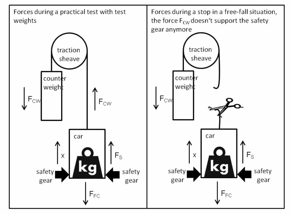
The difference between the requirement and the practical test is also physically substantial since it neglects all forces resulting from the counterweight when suspension ropes do exist. Parts of the weight force of the counterweight (FCW) act on the car through the suspension ropes in the same direction as the deceleration force of the safety gear (FS). In other words: the counterweight supports the safety gear in compensating the weight force of the fully loaded car (FFC). This support does not exist in the worst case when suspension ropes no longer exist. The following illustrations of an extremely simplified model show the forces at the moment the car makes an emergency stop during a practical test with test weights and when it makes a stop in a free-fall situation.
One may assume that the moment the safety gear is tripped the forces FCW of the counterweight are practically zero since the counterweight which is accelerated upwards continues to move upwards because of its intertia and that therefore the ropes between the counterweight and car would slacken for a moment. Exactly at that moment in time the practical test would be equal to the actual requirement of a free-fall stop. But this is not the case at all as has been proven by numerous practical measurements. Decisive factors preventing this are the ropes acting as long springs which first have to slacken again depending on their spring constant. Since the actual decelerating process only lasts a few milliseconds, this is something that happens extremely seldom.
(solid: acceleration, hatched: load in suspension ropes, dotted: speed)
Time T1: Acceleration: 0.0 m/s² Force: 28 kN Speed: -1.3 m/s
Time T2: Acceleration: 2.3 m/s² Force: 11 kN Speed: -0.7 m/s
Time T3: Acceleration: -0.7 m/s² Force: 2 kN Speed: 0.0 m/s
Illustration 2 clearly shows that the force in the suspension ropes is continuously reduced (hatched curve) during the entire safety gear operation (T1-T3). At the beginning of the safety gear operation the force is 28 kN. At time T2 when the car has already been decelerated to half the tripping speed of the overspeed limiter, it is still 11 kN and at the end of the safety gear operation it is still 2 kN.
Neglecting this force would mean a calculated deceleration of the fully loaded car in a free-fall situation of 12 m/s² (~ 1.2 g). But this result is incorrect! In reality a free-fall scenario would yield a deceleration of merely 3 m/s² (~ 0.3g) which would prevent serious personal injury in this elevator system.
Empiric experiments have shown that these influences stemming from the counterweight during safety gear trials with an empty car and averaged throughout the duration of the actual safety gear operation correspond to about 50% of the weight force of the fully loaded car. And the influence is even stronger with a fully loaded car since the decelerations achieved at the car and thus the deceleration difference between the counterweight and car are substantially smaller.
The model presented in illustration 2 has the following movement equation:

in which the acceleration and the forces depend on the time. In the following, simplified average values during the safety gear operation are examined at the interval ![]()
between tstart and tend, the same designations being used, for example:
This yields an average safety gear force with an empty car of:

The effective stopping distance in the optimum deceleration phase is calculated from the mean deceleration and the speed v at the start of deceleration by a double integration:

The safety gear force for a car packed with the rated load mrl then amounts to:

Assuming that the safety gear force during a downward ride of a car with only a small load or of an empty car is at least not smaller than the one of a fully loaded car, these two forces can be regarded as being equal FS,E = FS,F and can be used to calculate the deceleration by the safety gear at rated load. This procedure is allowed since the theoretical deceleration force of the safety gear depends neither on the initial speed nor on the car load. These parameters only affect the resulting stopping distance and deceleration.
A better presentation is given by showing the forces resulting from the counterweight as a multiple a of the car load:

A few transformations then yield the deceleration by the safety gear with a rated load:

These equations allow two interesting conclusions to be drawn:
- The deceleration of the car is highly dependent on the forces resulting from the counterweight. As already mentioned earlier, the average forces resulting from the counterweight often correspond to half the weight force of the fully loaded car. When this is entered in equation (4), it becomes apparent very quickly that this substantially influences the decelerations and/or the length of the sliding distance. The results of these characteristics are clearly bettered by the influences of the counterweight than they would be improved in a worst-case scenario with ruptured ropes.
- Equation (5) clearly shows that it is possible to use the deceleration during the safety gear operation with an empty car to determine the deceleration and thus also the sliding distance for a fully loaded car in a free-fall situation when the weight and the rated load of the car and the counterweight forces are known. This element is used by the electronic testing systems referred to earlier and will be dealt with once again later.
4. Effects of the Counterweight on the Inspection Statement
It is now of interest to apply these reflections to the current common practice of inspecting safety gears with test weights, requiring a difference to be made between inspections carried out before elevator systems are placed on the market and recurring inspections.
4.1 Inspecting the safety gear before the system is placed on the market
When the system is placed on the market one can hopefully assume that the real weights of the counterweight and car conform to the design criteria on the basis of which the safety gear has been selected. It must further be assumed that the system has been installed correctly and that for example the counterweight or car guides do not jam which would impermissibly support the safety gear in deceleration.
The selected safety gear has also generally passed a type examination and so has proven that it is capable of decelerating the specified loads down to a complete halt even in a free-fall situation without certain deceleration thresholds being exceeded.
But if one takes a look at the two principal testing criteria specified in safety standards all over the world and knowing the influence stemming from the counterweight, some obvious weak points cannot be ignored
4.1.1 Testing criterion: measurement of the sliding distance
An inspection principle such as the one specified in the North American ASME A17.1-2010/CSA B44-10 for example is decelerating the fully loaded car running at overspeed to a complete stop using the safety gear followed by a measurement of the sliding distance using the marks on the guide rails. In ASME A17.1-2010/CSA B44-10, Table 2.17.3 “Maximum and minimum stopping distances for Type B car safeties with rated load and Type B counterweight safeties”, a minimum and/or maximum limit is specified that needs to be reached.
For cars with a rated speed of 1.25 m/s for example the standard specifies a tripping speed of the overspeed limiter of 1.7 m/s, a minimum stopping distance of 150 mm and a maximum stopping distance of 675 mm.
If one then uses equation (4) to calculate the average force of the safety gear which is in the end evidenced at tripping speed and maximum stopping distance, a car with an empty weight of 2300 kg and a load of 1100 kg resulting in FS,F = 40633 N – FCW,F .
In contrast there is a force of 33354 N in a free-fall scenario which would make this car crash. It is absolutely clear that the force FCW,F produced by the counterweight must not exceed 7279 N because this would prevent the safety gear from decelerating the car. This merely corresponds to 22 % of the weight force of the fully loaded car. In this system that really exists in North America the counterweight influence is nearly 50 %.
This yields the frightening result that although the effectiveness of this safety gear in accordance with the valid standard about the determination of the slide distance is theoretically correct, this fully loaded cabin could not be brought to a complete stop in case of a free-fall scenario.
4.1.2 Testing criterion: measuring the deceleration
The other testing criterions for example specified in the European standard DIN EN 81-1:2010-06 in chapter 9.8.4 for brake safety gears are limit values for a deceleration in a free-fall situation (regardless of the actual load) of at least 0.2g and maximum 1.0g. This is tested by bringing the car with 125 % of the rated load to a complete stop.
Here, too, the problem is that the test is never carried out with cut suspension ropes and that the counterweight influences are unknown. So this testing criterion, too, does not allow a statement to be made about the effectiveness of the safety gear in a free-fall situation. Under certain aspects this may lead to the same disastrous conditions described under the sliding distance testing criterion.
The remarks made with respect to the test with weights prior to placing the system on the market illustrate that the effectiveness of the safety is actually not comprehensively tested since the counterweight influences are not known.
In the end one has to rely on the quality of the work carried out by the installation company, on the type examination of the safety gear and first and foremost on the correctness of the calculated weights of the counterweight and car.
4.2 Recurring safety gear inspection
In principle recurring inspections of safety gears are governed by the same principles already mentioned for inspections prior to placing systems on the market. But now the influential factor time is added.
The elevator system may have been modernised in the meantime. This often goes hand in hand with an increase of the car weight. The company carrying out the modernisation has usually restored the counterweight balance by increasing its weight. As such the forces resulting from the counterweight may have increased when the safety gear is inspected so that the test result is even less useful for proving the safety gear’s effectiveness.
Depending on the servicing condition and the time the elevator system was been in operation there may be wear on the safety gears, guides, etc. In some cases this is another factor that contributes to an increase of the forces resulting from the counterweight.
5. Inspecting the Safety Gear Using Electronic Test Systems
As shown by the equations it is possible to determine the deceleration of a fully loaded car in a free-fall scenario from the deceleration of the safety gear tested with an empty car provided the counterweight influences are known. This principle is based on the fact that the force of a brake and thus of the safety gear develops independently of the weight to be decelerated or its speed. For elevator systems this means that the safety gear must be fully engaged and in this condition must always apply the same deceleration force. This deceleration force can be determined by measuring the car’s deceleration and the forces resulting from the counterweight during the safety gear operation. Once this deceleration force is determined, it is easy to calculate the average deceleration of the elevator in a free-fall situation for any random load and initial speed.
Modern electronic testing systems therefore consist of two principal components: an acceleration sensor mounted on the car and force sensors measuring the forces in the suspension ropes immediately above the car during the safety gear operation. Then the equations referred to earlier are used for the calculation of the safety gear’s effectiveness. Since these systems are in use in Germany and recently also in North America numerous elevator systems have been identified in which the safety gear’s effectiveness could not be verified although they had been inspected at recurring intervals in the past, but with test weights and without knowing the counterweight influences.
The physical superiority of this measuring principle with respect to a possible statement about the effectiveness of the safety gear is obvious. Another factor often neglected needs to be added: an important argument for inspections with test weights is the installation and material quality test carried out at the same time in form of a mechanical elevator system stress test. Any shortcomings are revealed by a visual inspection after the safety gear operation ends up in distorted cars, destroyed internal panellings, etc.
But it applies to an even greater extent to the test without test weights. Since the deceleration force of the safety gear is the same in this test as in the test with weights, decelerations are much higher and the stopping distance is much shorter.
The clearly higher and more abrupt deceleration therefore also causes a substantially higher mechanical stress for the elevator system. A stress which in a worst-case scenario with for example only one passenger needs to be endured.
6. Summary
This paper has made it clear that a test of the safety gear using test weights and without determining the influences of the counterweight does not allow a statement to be made about the effectiveness of the safety gear, neither before it is placed on the market nor during recurring inspections.
In Europe for example the requirement specified in EN81 with respect to deceleration limits in a free-fall situation is not tested.
Surely the increase of the safety level is one of the reasons why the current 2013 edition of the North American elevator standard A17/B44 has permitted electronic testing systems, if only as an option. Inspections using test weights are still allowed and are even mandatory prior to placing the system on the market.
Since inspections without test weights are also accompanied by a substantial mechanical stress test for the elevator system, it must be allowed to question the justification of the safety gear inspection using test weights and to ask if the use of electronic testing systems does not provide a much higher level of reliability and safety.
Biographical Details
Tim Ebeling has been employed since 2003 as head of development with Henning GmbH & Co. KG. In this capacity he has established the R&D center in Braunschweig (Germany). A team of employees is now working there on the development and production of electronic and measurement components for lifts.
Since 2012 the author is also managing director. One of his particular focal points is the measurement technology. Especially in this area the author looks back on many years of experience in the development of acceleration and rope load measuring systems.
The author’s professional goal is to enrich the elevator market with innovative elevator compo-nents and opposing the increased cost pressure in the elevator industry through the develop-ment of efficient sustainable and labor-saving components.
Get more of Elevator World. Sign up for our free e-newsletter.


