A consultant’s assessment
A recent lift traction design review focused my attention upon system design and the relationship between the EN 81-20 fatigue-based calculation of the suspension rope safety factor and a consideration of the rope-specific pressure originally developed almost 100 years ago by Hymans and Heilborn.
This is the second occasion on which I have encountered the dubious proposition that “as a measure of rope pressure is no longer prescribed in EN 81, it therefore need not be considered.” In both of these instances, the maximum permissible pressure was exceeded by a significant margin.
The expression of this misunderstanding or falsity often arises to disguise a deficient traction design and, of course, a decision to ignore the underlying assumption of EN 81-20 0.4.3.a) that:
“Relevant risks have been considered for each component that may be incorporated in a complete lift installation and rules have been drawn up accordingly:
Components are:
a) designed in accordance with usual engineering practice (see FprCEN/TR 81-12) and calculation codes, taking into account all failure modes;”
Whilst rope pressure was a foundational principle underlying the ASME A17 Elevator Code, its prescription in the 1977 EN 81-1 Standard, replacing the previous reliance upon what were often arbitrary rope safety factors, established rope pressure as a safety measure in Europe, which continued through to 1999, with a requirement that, in the case of the car loaded with its rated load at the lowest floor, in no case should the specific pressure of the ropes exceed:
Where p is the specific pressure in N/mm2 and vc is the rope speed corresponding to the car speed.
The 1977 and 1985 EN 81-1 Standards also provided that it was the responsibility of the lift manufacturer, taking into account the individual characteristics and conditions of use of the lift, to consider the choice of rope pressure.
My experience is that responsible and competent designers consider the fatigue-based EN 81-20 calculation in conjunction with the rope-specific pressure such as to achieve a safe and resilient design in terms of the characteristics of a particular lift. This involves consideration of a range of factors including the installed environment; rope and sheave diameters; diverter pulley diameters; bends and reverse bends; rope construction; the number of ropes; lift usage; safety factors; groove profile; and groove pressure. All of these factors are balanced, such as to produce a safe, efficient and resilient system design.
EN 81-20 Assumption 0.4.12 is sometimes cited as an excuse for, or in defence of, a questionable traction design and provides:
“With the exception of the items listed below which have been given special consideration, a mechanical device built according to good practice and the requirements of the standard, including uncontrolled slipping of the ropes on the traction sheave will not deteriorate to a point of creating hazard without the possibility of detection provided that all of the instructions given by the manufacturer have been duly applied:”
The purpose of Assumption 0.4.12 is for designers to ensure that key safety provisions and components, including the traction sheave groove, which are subject to wear, are designed such that their condition is readily assessable and that instructions associated with such assessment are provided. It is not, and never was, to provide a loophole to justify reckless or inept traction design.
In this respect, a question of the ethical principles underlying engineering design arises in terms of the transfer of equipment design risks, which are best minimised and/or mitigated at the design stage, onto future maintenance. This approach represents no more than a reduction in capital cost at the expense of an unknowing future user and/or maintainer to whom the duty to, and cost of, managing the risk, which should have been designed-out, is transferred.
Excessively high rope pressures arising due to reductions in sheave and rope diameter, which should have been readily eliminated in the original equipment design, together with the associated increased risks (in both safety and cost) are transferred from the capital cost to the end user, who is more often unaware of what has occurred. In effect, this represents a transfer of design risk from an unscrupulous and/or inept designer to an unwitting client.
Uncertainties relating to the assessment of the depth and consistency of the surface hardening of V-profile sheave grooves are well understood, in that designs involving unduly high rope pressure introduce additional safety risks which should be eliminated at the design stage, and which may subsequently prove difficult to manage.
Whilst it has been suggested to me that the Hymans and Heilborn method may be outdated, I would suggest that its continuing longevity — almost 100 years now since inception — speaks for itself! And I also note that it was necessary for the definition of different groove profiles, together with the data underlying the EN 81-1: 1998 fatigue-based calculation, to be updated in EN 81-20 in order to render the calculation more robust and to correct what were clear errors in the original 1998 Standard. To be fair though, I recall that the EN 81-1/2: 1998 Standards were prepared and published in some haste in order that these should be available for the 1999 implementation of the 1995 Lifts Directive.
The fatigue calculation introduced in EN 81-1: 1998 coincided with the emergence of the machine-room-less (MRL) lift and, when considered with other relevant factors including rope pressure, provides a reasonable approach to the increased number of pulleys and bending cycles inherent to the majority of MRL designs.
I recall that Otis Elevator Co. developed the work of Hymans and Heilborn and traditionally applied no less than five duty classes in relation to traction design and the assessment of rope pressure which included:
- Maximum Service — 8 to 10 h per day — Lifts running on schedule. Typically, offices and department stores.
- Average Passenger Service — One or more lifts in the building not running on schedule, but answering calls as required.
- Intermittent Passenger Service — Similar to Average Passenger Service, but where car stops and mileage are low and where full rated load is carried infrequently. Typically, certain hospitals or apartment buildings
- Average Freight Service — Similar to Average Passenger Service but with extended periods at rest corresponding to average handling of freight. Typically, certain hospital lifts may fall into this category.
- Intermittent Freight Service — Long periods at rest. Typically, garages, small warehouses and buildings in less congested districts.
The engineering factors considered in relation to the service duty were those which prevail today, including loading; rope diameter and rope speed; sheave diameter; and groove profile.
One could tolerably apply a higher rope pressure in an application which was subject to a reduced number of starts without compromising the safety of the equipment or the service life of the traction sheave and suspension ropes. Indeed, Otis produced a series of curves relating to its range of machines, sheave diameters, different groove profiles and their application in different duties. The Otis approach is reflected in that adopted somewhat later by Professor Janovsky in his adaption of the Hymans and Heilborn approach, which relates the number of lift starts to an acceptable rope pressure, albeit that it should be noted that even for a calculation as low as 60 starts per hour Professor Janovsky’s calculation never encroaches upon the traditional Hymans and Heilborn maximum.
Where k is the coefficient relating to lift usage expressed as the number of trips per hour (Janovsky L):
Where z is the number of trips per hour (Janovsky L).
Rope pressure is integral to the traction drive itself, with an adequate level of rope pressure critical to maintain the contact necessary to safely drive the lift (or prevent its being driven in the case of a stalled counterweight), and in this sense, the proposition that rope pressure may be ignored in traction design is nonsensical.
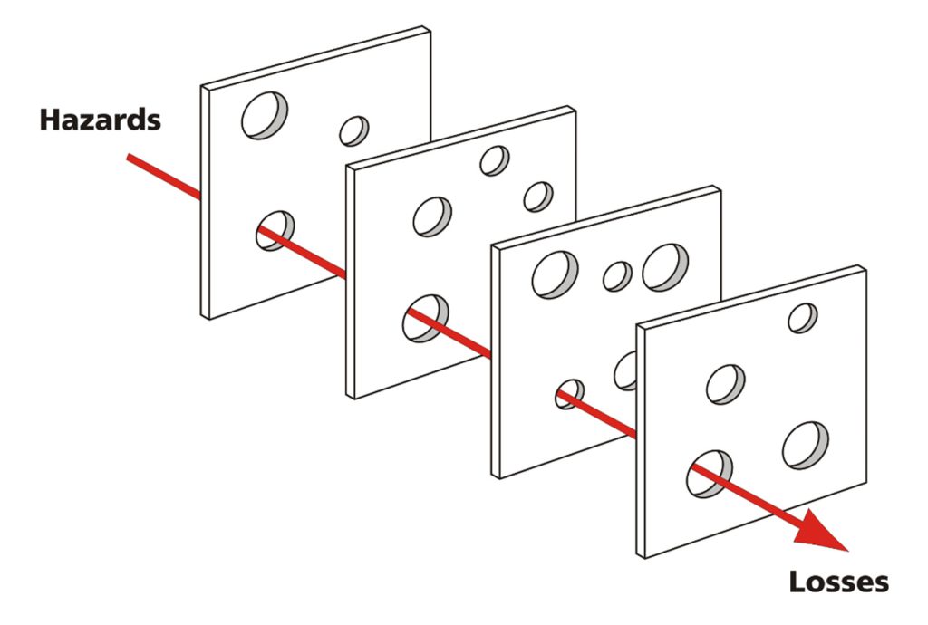
A shortfall in an engineering system design may not become manifest until the equipment has been in use for a time (after the designer is long gone). This may serve, consciously or unconsciously, in the minds of those engaged in the design shortfall, to justify a deficient design. However, the underlying reality, supported by experience, is that such built-in shortfalls exhibit a tendency to emerge in conjunction with other, sometimes unrelated, system deficiencies in the form of failures and accidents and/or as unintended or unforeseen consequences of the original decision. The concept is illustrated in James Reason’s Swiss Cheese model of systems failure (Figure 1) in which a series of defences (in our case the provisions of our industry engineering practice, Standards and Guidance) are modelled as slices of Swiss Cheese, which operate concurrently to form a series of defences against failure. The effect of a designer ignoring, contravening or shortcutting elements of a Standard, be these implied or explicit, is equivalent to omitting one or more of Reason’s Swiss Cheese slice defences, and introducing system level deficiencies which become manifest in failure during the life of the equipment (in aligning the holes in the Swiss Cheese slices). In our industry, the effect of introducing deficiencies or shortcuts in relation to the underlying intent inherent in the requirements of our Standards and Regulation is to reduce overall system resilience and increase the overall level of risk inherent to a particular design.
My experience working as an expert in a number of fatal accidents has been that a single source of failure is rarely, if ever, causative, but that it is the cumulative effects of design deficiencies, often compounded by shortfalls in maintenance application, which underly an accident. The design shortfalls (contrary to requirements of the EN 81 Standards and/or good engineering practice) may have appeared innocuous to the original designer, but when combined with other issues at some time in the future, lead to catastrophic outcomes. And the approach adopted by an enforcement authority, with the clarity of hindsight, is inevitably focused upon the original deficient design in a “but for the design defect,” the accident would not have occurred, scenario.
A second concern relates to the marketing of MRL lift packages which incorporate reduced-size lift machines and a sheave-to-suspension rope diameter ratio (Dt/dr) of less than the 40:1 prescribed in EN 81 20, and which is the minimum ratio prescribed in most jurisdictions. An example I encountered was justified by way of a Notified Body Approval, albeit that the outcome was of a reduced lift service duty (number of trips) and suspension rope life, of which the end user/purchaser would be unaware until it was too late. The 40:1 minimum sheave-to-rope diameter ratio was, I had thought, considered sacrosanct in terms of safe and effective lift design. Indeed, I am sure that the original drafters of the Lifts Directive and associated EN 81 Standards never conceived that this long-standing safety provision would in the future be subject to interpretation and circumvention by a Notified Body, or by anyone else for that matter. The effect of this ill-conceived approach is to undermine the purpose of the Lifts Directive in establishing a high level of protection of health and safety together with a level of transparency, such as to guarantee the functioning of the EU internal market. In effect, the approach reduces levels of consumer safety and confidence. A conservative approach to safety design is fundamental and, in my experience of more than 50 years in the industry, is such that I am a subscriber to Murphy’s Law: “If it can go wrong, it will go wrong.” The onus is on us as ethical and professional designers to design-out potential hazards, risks and failure modes at the source, such as to produce safe, efficient and sustainable products, which are fit for purpose — and not to seek to displace risks that should be mitigated through effective design by transferring these to end users and/or maintainers.
One of these designs was installed with a suspension rope life measurable in weeks and with regular machine bearing failures. Faced with the prospect of litigation, the contractor corrected the installation.
The responsible designer is aware of the difference between compliance and quality and that our industry Standards represent the minimum levels of safety to be achieved. All too often, I encounter designs which are said to be compliant (which is often questionable) but which cannot, by any measure, be considered quality designs. I believe this situation has arisen due to a lack of in-depth understanding and engineering experience on the part of designers who have entered the industry over the last 20 years or so, together with a lax approach by a few designers who should know better. Compliance is not quality!
Get more of Elevator World. Sign up for our free e-newsletter.
