Sensorless Speed Control of PMSM for Elevator Systems
Nov 1, 2012
Energy efficiency, cost and other aspects are taken into consideration when examining permanent-magnet, synchronous-motor (PMSM) sensorless speed control.
by Li Xiangwei, Luo Zhiqun and Wan Jianru
The performance of an elevator system greatly depends on the performance of its traction machine and control method. Energy efficiency, cost and other aspects are taken into consideration when examining permanent-magnet, synchronous-motor (PMSM) sensorless speed control. Sliding-mode control (SMC) is robust against parameter fluctuations and disturbances, while model-reference adaptive systems (MRASes) can adjust model output according to the output of the reference and adjustable models. In order to improve the estimated accuracy of the rotor speed and flux, both methods are combined. Simulation and experimental results verify the control method is robust against fluctuations and disturbances of the rotor speed and torque, which reflects good system robustness.
Introduction
For passengers, requirements of elevators are security, comfort, high speed, small oscillation, etc. For elevator designers and manufacturers, requirements include energy savings, efficiency, low cost, convenient maintenance, etc. Therefore, elevator systems should meet both parties’ requirements, as well as high-performance standards. Since the system depends on the performance of the traction machine and control model, choosing the appropriate motor structure and control model for the system is critical.
The speed drive mode of PMSM units is currently a main research focus in elevator-drive technology because of characteristics such as low noise, high precision, comfort, ease of use, etc. However, traditional mechanical sensors are susceptible to the influences of temperature, humidity and other environmental conditions. The interference immunity and stability of the system are poor, and the sensor itself and its auxiliary circuit are expensive; therefore, sensorless speed control is becoming a research focus.[1]
This article will discuss the advantages of SMC and MRAS to estimate the rotor speed of a PMSM, construct an error state equation to estimate the speed and flux of the rotor more accurately and realize sensorless speed control.
Sliding-Mode Variable Structure MRAS Observer Construction Fundamentals of MRAS
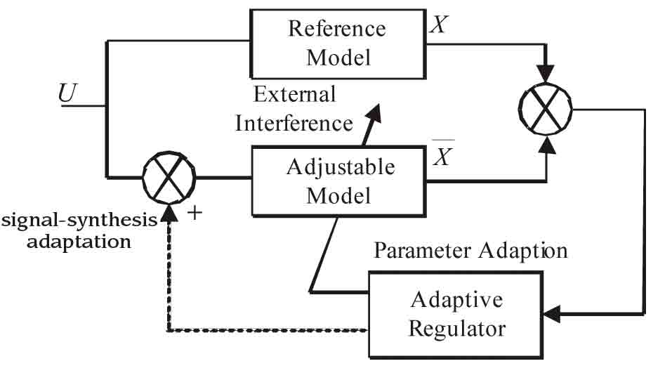
The MRAS estimator uses two models: One is a reference model without an unknown parameter, and the other is an adjustable model with an unknown parameter. Both have the same output. The error of these actual and estimated outputs is fed to the adaptation mechanism to estimate the adjustable parameter that tunes the adjustable model in order to drive the output error between these models to zero.[2&3] The system structure is given in Figure 1.
The aim of using variable-structure MRAS to identify speed is to search for the equivalent speed weq so the actual speed affected by random and uncertainty can follow the given one; that is:
lim ei(t) = 0
t ![]() ∞
∞

State Error Equation Construction
Since the stator current equation in the d – q axis reference frame contains parameter w, the current equation is taken as the adjustable model, while the actual motor is used as the reference model.[1] Note, Ld = Lq = L in surface permanent-magnet (SPM) motors, and an adjustable model matrix form is given as:
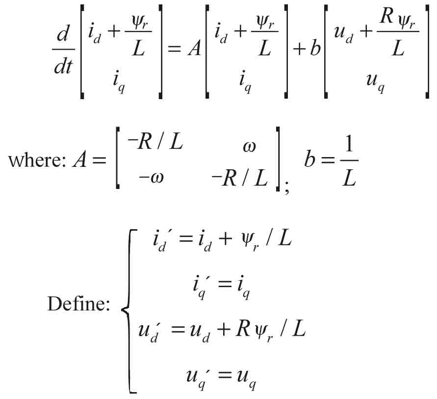
Then, equation 1 can be simplified:
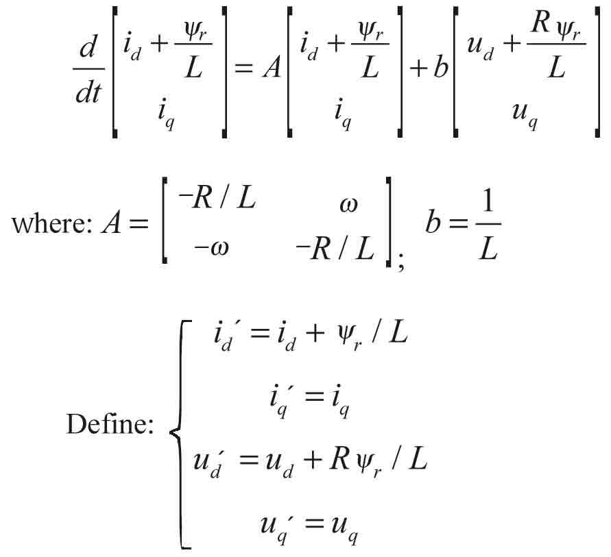
The estimated model can be simplified as follows:
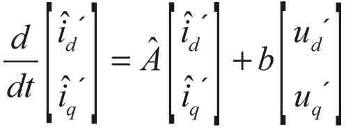

and q-axis stator current estimated values, respectively. The estimated value of angular speed is.
The estimated module can be written as ![]()
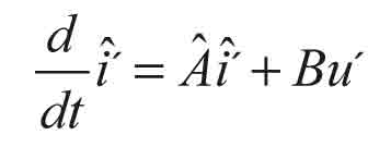
State errors can be defined as ei ![]()
Taking the time derivative of ei, we find
(Equation 5)
Design of Sliding Surface
When the equation S(x) = S'(x) = 0 is satisfied, the sliding mode observer can reach the sliding surface in limited time and stay on it.
When the sliding mode is reached, S(e) will be equal to zero, sliding movement with good dynamic performance is asymptotically stable. According to the principle, the MRAS speed observer’s switching function of variable structure can be obtained as

Equation 1 minus Equation 4 can reach state error

When the system is stable, the error is almost zero:

By substituting Equation 2 into Equation 8, the state error is represented as

Compared with the general sliding surface, integral sliding surface has the following advantages: The motor torque can be much smoother, the steady-state error of the system can be reduced and the chattering can be reduced.[4] For this article, the integral sliding surface was selected, which is shown as follows:

where k denotes the integral gain.
Rotate Speed Estimation
Based on Equation 1, taking the time derivative of S, we get

where f(x) is the function of reference currents id, iq, estimate currents , , voltages ud, uq, rotor angular speed w, rotor flux yr, stator resistor R and stator inductance L.
From Equation 10, it can be known that

is always satisfied. So, an M surely exists, and all spot points near the switching surface area are approaching to the surface when the M is big enough; i.e., the following inequalities are satisfied:


From Equation 12, we know that when the estimated current value is equal to the reference value, equivalent speed is equal to real speed.
Using sine function, speed observer expression can be written as

To suppress and eliminate chattering in the process of sliding-mode control, and to estimate rotor speed and flux more accurately, traditional sine function is replaced by sigmod function. Sigmod function is given in Equation 14.[5]
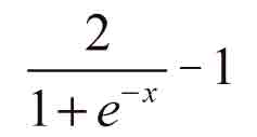
Then, the speed observer can be expressed as

where M is a constant greater than zero. According to Popov’s hyperstability theory, the low-frequency components of are the equivalent speed.
Simulation Results
Simulation parameters are set as follows: outer-loop PI controller: Kp = 5, KI = 6; inner loop PI controller: Kp = 0.01, KI = 0.01; sliding-mode variable structure MRAS speed observer parameter: M = 3,000; integral sliding surface parameter: k = 10; and low pass filter bandwidth: 120 Hz.
Simulation conditions are set as follows: step change in motor speed from 2,000 to 2,500 rpm; abrupt load torque change from 1 to 4 N·m, while the motor runs at 2,500 rpm. The feasibility of this algorithm is proved by observing the estimated and actual waveforms of the rotor speed and angle.
The waveforms are shown in Figures 2 and 3:
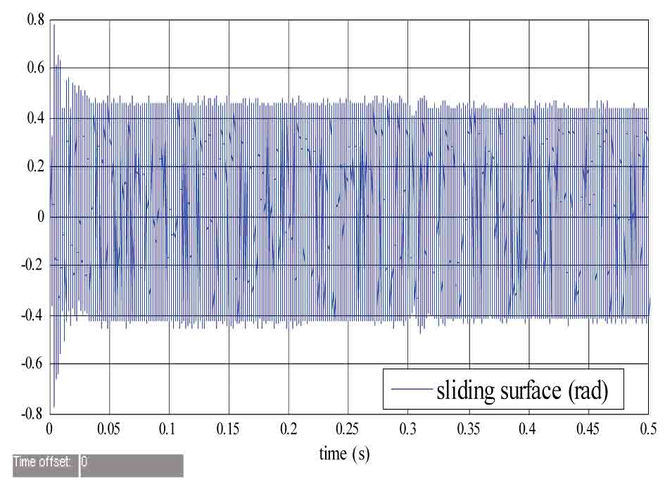
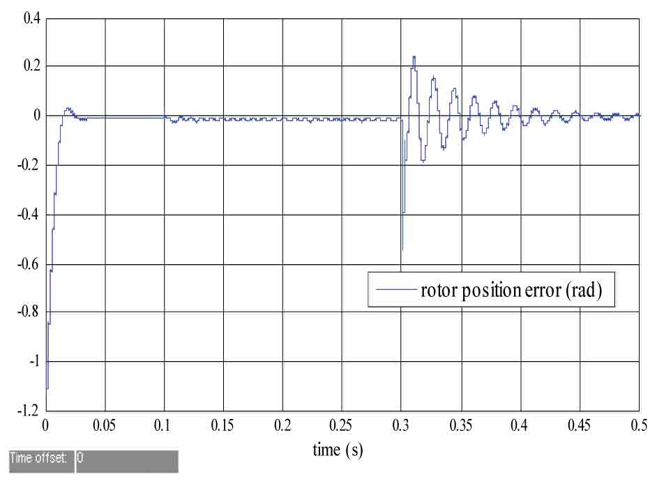
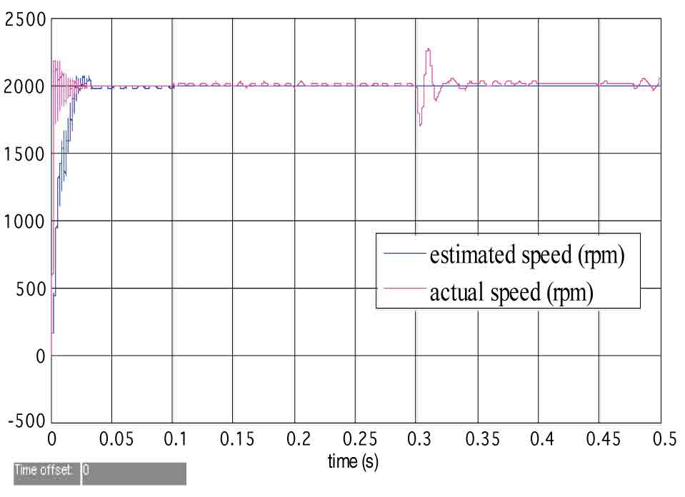
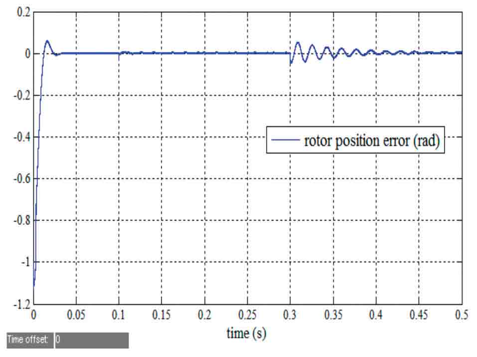
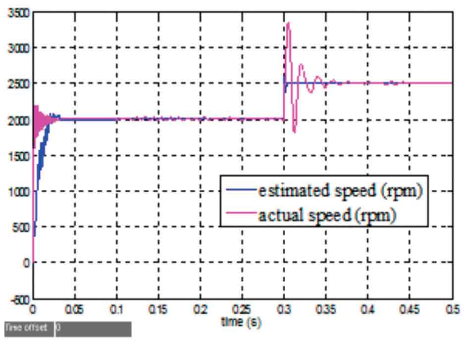
Figure 2(a-c) illustrate waveform motor-speed steps from 2,000 to 2,500 rpm, which are used to observe the response and dynamic performance of the system based on sliding-mode variable structure MRAS and PMSM-DTC when speed steps. As shown in Figure 2(a), the sliding surface passes through around zero value, and waving width reduces slightly. All these illustrate the sliding mode crossover frequency increases to some extent but remains steady. Figure 2(b) shows observer tracking performance is good, steady-state error is small and the speed response can be fast and stable when speed steps. In Figure 2(c), the error between estimated and actual rotor angles almost stabilizes at zero. There is a pulse when speed steps, but it can still reach a new steady state. Steady-state error is low and will not affect the performance of the system.
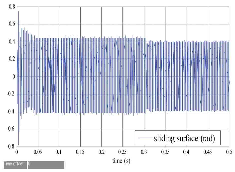
Figure 3(a-c) represent simulation waveforms when an abrupt load torque from 1 to 4 N·m is applied while the motor rotates at 2,500 rpm. The waveforms are used to observe the robustness of the system when load torque changes abruptly. As shown in Figure 3(a), after torque changes abruptly, switching width reduces, and times and frequencies of passing through the sliding surface increase but remain stable. Figure 3(b) shows significant speed drops when the torque changes abruptly, but after a period of adjustment, it is able to return to a steady state, and the steady-state error is minimal. In Figure 3(c), the error between estimated and actual rotor angles almost stabilizes at zero. There is a pulse when torque changes abruptly, but it can still reach a new steady state. Steady-state error is low, which will not affect performance of the system.
Experimental Results
The parameters of PMSM systems discussed in this article are shown as follows: rated voltage: 380 V, rated current: 1.5 A, rated power: 550 W, rated speed: 1,500 rpm. The DC motor is coaxially connected with the PMSM as load. The performances of the sliding-mode variable structure MRAS and PMSM-DTC in this article are verified based on hardware circuit and C programming language.
Experimental conditions are as follows: speed steps from 800 to 1,000 rpm, and torque changes abruptly at 1,000 rpm. The feasibility of this method is verified by observing the speed waveforms. The waveforms are shown separately in Figures 4 and 5.
Figure 4 shows the speed waveform when the motor speed steps from 800 to 1,000 rpm. Channel (CH) 1 is the speed sensor output, and CH 2 is the proposed observer estimated output. Figure 4 shows that when there are speed disturbances, there is no jump at estimated speed, which is still stable and capable of tracking real speed.
Figure 5 shows the speed waveform when torque changes abruptly at 1,000 rpm. CH 1 is the speed sensor output, and CH 2 is the proposed observer estimated speed. Figure 5 also shows that when there are torque disturbances, there is no jump in estimated speed, which is still stable and capable of tracking real speed.
Conclusion
The method proposed in this article combines two advantages.
Simulation and experimental results show that the proposed speed sensorless control system based on variable structure MRAS and PMSM-DTC has an invariant property of abrupt disturbance both of speed and torque, can reach a new steady state in a short time and reflects the system’s robustness.
References
[1] Liu Yingpei (2007). Research on PMSM Speed Sensorless Control for Elevator Drive [D], Tian jin: Tianjin University.
[2] Geng Jie, Chen Zhen, Liu Xiangdong and Lai Zhilin (2011). Adaptive Inverse Control of Permanent Magnet Synchronous Motor [J], Transactions of China Electrotechnical Society, 26(6): p. 50-55.
[3] Laick, Kuoks (2005). A Novel Motor Drive Design for Incremental Motion System Via Sliding-Mode Control Method [J], IEEE, Trans on Industrial Electronics, 52(2): p. 499-507.
[4] Tong Kewen, Zhang Xing and Zhang Yi (2008). Sliding Mode Variable Structure Control of Permanent Magnet Synchronous Machine Based on a Novel Reaching Law [J], Proceedings of the CSEE, 28(21): p. 102-106.
[5] Hongryel Kim, Jubum Son and Jangmyung Lee (2011). A High-Speed Sliding-Mode Observer for the Sensorless Speed Control of a PMSM [J], IEEE, Transactions on Industrial Electronics, 58 (9): p. 4069-4077.
Get more of Elevator World. Sign up for our free e-newsletter.
