Small Ropes – Aspects for Usage in Elevator Application
Jul 1, 2011
This research examines the effects and usage of small-diameter suspension ropes.
This paper was presented at  Lucerne 2010, the International Congress on Vertical Transportation Technologies and first published in IAEE book Elevator Technology 18, edited by A. Lustig. It is a reprint with permission from the International Association of Elevator Engineers
  (website: www.elevcon.com). This paper is an exact reprint and has not been edited by ELEVATOR WORLD.
Abstract
The use of suspension ropes of less than 8 mm in diameter will increase in numerous elevator installations. Elevator product series have already been developed for several years. Special-design ropes for these applications, when compared with the conventional lift components included in the standard, require greater effort in design approval and acceptance of the actual lift. Test certificates issued by Notified Bodies are used to support producers, certifying the suitability of the special-design ropes for use as elevator suspension ropes. A summary shows the availability of certificates covering all applications also out of minimum number of trips deposited in EN81-1. The fact of separate expert evaluation for these ropes makes it permissible both to go below D/d = 40 and also to go below the 8 mm minimum diameter for ropes specified in the standard. Absolutely necessary is a clarification of the expectation of users and the life time of ropes in the practical application best before planning and contracting phase. The material of the deflection sheaves is discussed very often in case of reliable detection of rope discard. The influence of plastic sheaves on lifetime and discard will be presented.
1.Introduction
Pressure on costs and a tougher competitive environment have led variously to technical solutions that are shaped solely by cost optimization parameters. Yet amid all these cost capping discussions, we should never ignore safety and reliability requirements – especially with traction sheave elevators which are of such safety-related and public-interest concern.
The machine element steel wire rope is the core element in any elevator system, affecting performance characteristics and system costs. Thinner ropes, with the same diameter ratio of traction sheave to steel wire rope D/d, lead to smaller sheaves and smaller drive units with lower (cost determining) output torques. However, smaller sheave diameters also permit smaller installation space and, consequently, reduced head room. Larger cabin floor areas are possible. But what about safety- related requirements, when the steel wire rope is running, which are: service life and the point of wire rope discard? As they run over the sheaves, steel wire ropes are exposed to a range of strains such as primary and secondary tensile stresses, bending stresses, pressure and torsional stresses – as well as wear and tear due to relative motions between rope and sheave and within the wires themselves. It is precisely because of this kind of attrition that the service life of the steel wire ropes cannot be computed direct even if there is adequate knowledge of the wire stresses; instead, that service life has to be ascertained via fatigue bending tests. The bending fatigue test rigs deployed for this purpose, the test procedures and the statistical evaluation are set out in detail in Feyrer2002. It may be noted here that – in addition to bending length, nominal wire strength and rope diameter – the diameter ratio of sheave to rope as well as the rope tensile force have a significant effect on rope service life. These parameters therefore play a key role in “Feyrer’s rope service life equation” with which the results of fatigue bending tests, i.e. the ascertained number of bending cycles up to the point of discard, can be described. In Feyrer2002 it is standardized and/or frequently deployed rope constructions that tested and evaluated. Furthermore, Feyrer2002 includes the presentation of a method by which the deviation of the test results can be taken into account.
However, in the case of special rope construction such as e.g. the Pfeifer DRAKO STX 4, the existing test results should not be accepted too readily. On the contrary, the corresponding basic principles for the service life equation have to be re-created – this by means of adjusted fatigue bending tests with realistic test parameters such as the diameter ratio D/d and groove form etc.
In a first step, the diameter threshold of d ≥8mm was not adhered to. The diameter ratios between the sheave and the rope have been retained with D/d=40. In a first step the 4mm and 5mm ropes have been issued with product type test certificate G461 by TÜV Süd, Germany. This certification applies to elevator systems using traction sheaves with V-grooves of g =40° to g =50° and guide sheaves with round grooves at a diameter ratio D/d=40. In a further development, however, and for the above-mentioned reasons of cost, space requirement and use-able cabin floor area, the sheave diameter ratios were reduced to D/d=30. These small D/d ratios have finally been included in the type examination certificate G461/1. As regards the 250T Warrington 8×19 IWRC rope, it was also possible to at least reduce the D/d-thresholds defined in EN81-1 to d=6mm and d=6.5mm for the deflection pulleys – obviously after extensive lifetime tests had been performed – to D/d=25 (G491 and G491/1). All of the previously listed product type test certificates for small ropes
also have in common that the safety factor Sf pursuant to EN81-1, Annex N is calculated as a function of the number of pulleys in the rope zone which is subjected to the highest load, the groove form, etc. One development gives rise to the next and new demands and desires are awakened. In the product test type certificate G515, these safety factor thresholds are exceeded but without neglecting the safety demands placed on means of support. Only as a reminder, some sentences on the lifetime calculation of steel wire ropes with the steps fatigue tests, statistical calculations and cummulation process.
2. Lifetime Tests
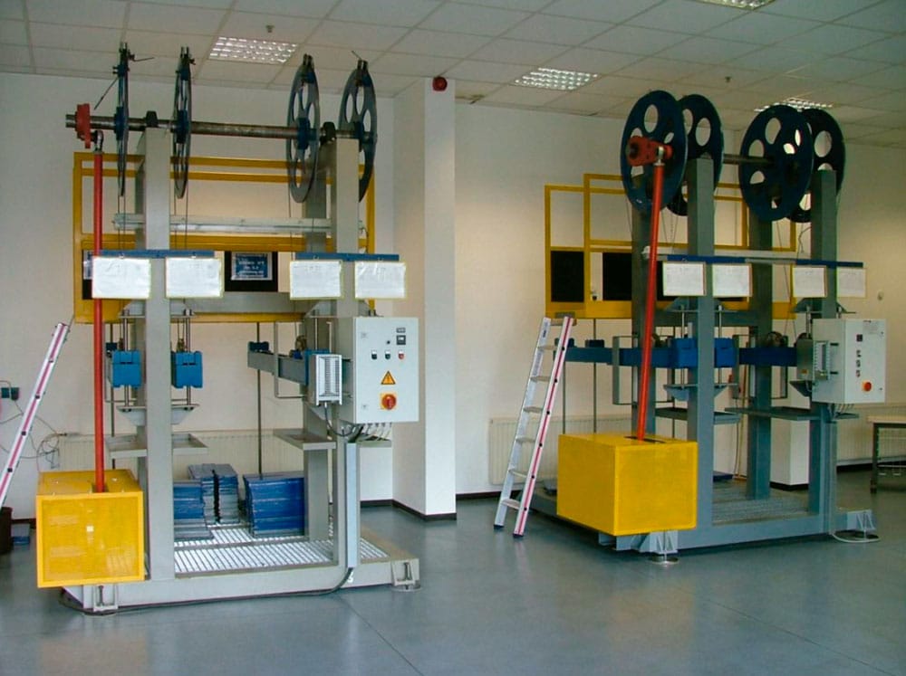
The test commences with bending fatigue tests, during which the test parameters diameter ratio from sheave to rope D/d, the tensile force of the rope and the groove are varied. Figure 1 shows the bending fatigue test rigs in the Pfeifer DRAKO Technical Competence Center in Mülheim a. d. Ruhr, Germany. These bending fatigue test rigs are practically identical with the machines described in Feyrer2002 and so, for this reason, we will dispense here with a detailed description and refer the reader to the literature.
All that needs to be borne in mind here is that, during the fatigue bending tests, wire breaks in the bending zones were counted for reference lengths of l=6xnominal rope diameter d and l=30xnominal rope diameter d and that the rope diameter was measured. The discard criteria for the STX 4 steel wire ropes to be applied are wire breaks for reference lengths l=30xd and l=6xd and a diameter decrease by 6% (which is intensified compared to DIN 15020 with its 10% against nominal rope diameter).
The test parameters for the fatigue bending tests are set in such a way that test duration can be kept within reasonable limits and that the information content in terms of subsequent elevator applications does not get submerged.
For the tests with the V-grooves or round grooves with undercut, we chose safety factors of Sf,min=10. These smallest safety factors do not actually occur in the subsequent application – i.e. the results of the fatigue bending tests have to be extrapolated to a certain extent. The same goes for the tests with the round grooves which were carried out with the relatively low safety factors
Sf <8. A comparison with the number of bending cycles as ascertained by Feyrer2002 – for similar rope constructions, with the rope safety factors tested and with the D/d ratios – shows that the DRAKO ropes achieves a fourfold higher number of bending cycles up to the point of dis-card. However, to stay on the safe side, smaller augmentation factors are used for the further calculation of the number of journeys expected up to the point of discard.
3. Probability Distribution and Deviation
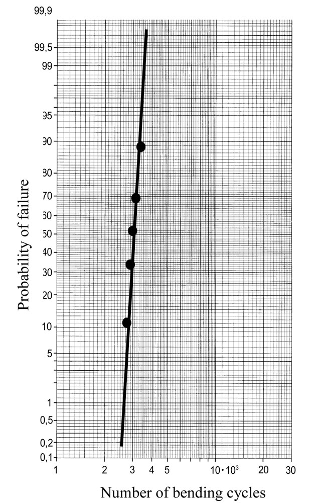
Other significant details – sometimes concealed beneath the basic requirements – include uniform rope tension within the ropes set out in parallel and the deviation of the rope properties within a given batch over a longer period of observation. Moreover, rope manufacturers must also be able to answer questions such as what influence does the deployment of plastic guide sheaves have on rope service life and, above all, on establishing the point of discard. Let us single out deviation by way of an example. From one production batch of STX 4 (Seale 6×17 WSC d=4mm) rope measuring approximately 8,000 m, we took rope specimens at five different places and subjected them to fatigue bending tests. The tests were all conducted on the same fatigue test rig using constant test parameters. The number of bending cycles up to the point of discard so ascertained were then recorded on a prob-ability graph – Figure 2. It can be stated that the number of bending cycles up to the point of discard can be described exceptionally well on the basis of logarithmic normal distribution. The deviation or the standard deviation – characterized by the steep course of the regression line – is with lgs=0.038 relatively small and lies at the lower margin of the deviation given in Feyrer2002 for several tests based on the same batch. The mean value is here even more than 2.5 times higher than literature based results. It can be stated too that the deviation for different production lots is in the same range.
4. Cummulation Process
To calculate the number of trips, the number of bending cycles up to the point of discard for the steel wire ropes in the round groove and form grooves was taken, this assuming that the highest-stressed section of rope runs over the traction sheave with form groove and over two guide sheaves with round groove with single bending, Figure 3.
According to the Palmgren-Miner rule, the number of trips to be expected is then

5. Type Examination Certificate G515
The definitions laid out in EN 81-1, Annex N result in a rope drive whose service life is limited and in many cases, for instance in the mid and high-rise sector, is considered low. It should be borne in mind here that the intention of this computation method is predominantly to satisfy safety objectives.
However, the world of lifts and elevators is highly diversified. In complete contrast to the highly frequented installations discussed above, in the field of residential lifts or when dealing with installations known to be little frequented, the definition provided by EN 81-1, Annex N is said to be too “lavish”. When dealing with this type of lift, the obvious solution is to design the rope drive in such a way that the D/d ratio and safety factors are reduced in order to save traction-related costs and also permit optimization of the installation space. However, as might be expected, smaller D/d ratios and rope safety factors result in a reduced rope service life.
For the DRAKO steel wire rope type 250T d = 6 mm, d = 6.5 mm and d = 8 mm, the number of trips to discard is calculated for practically any optional sheave-to-rope diameter ratios, safety factors independently of the EN 81-1 calculation and differently shaped sheave grooves. This applies here for a case in which the rope section ex-posed to the highest levels of stress runs over the traction sheave and two deflecting pulleys. Both identical diameters in the traction and deflecting pulleys DTraction sheave = DDeflecting pulley and different diameters DTraction sheave DDeflecting pulley are analysed.
For the traction sheaves, V-grooves from g = 35° to g = 60° and U-grooves with undercut angles b = 75° to b = 105° are used. Reduction factors in accordance with EN 81-1, Annex N are applied. Unlisted reduction factors are determined by extrapolation.
EN 81-1 is based on a minimum number of trips to dis-card age, which in some cases cannot be achieved with the above sheave-to-rope diameter ratios. The aim is now to demonstrate the number of trips which may be expected until discard age with the small D/d ratios for different rope safety factors Sf, differently shaped grooves and different sheave combinations.
As the parameters we are dealing with here are unconventional in the elevator construction sector, calculation errs on the side of safety, for instance by taking into con-sideration increases in rope force due to uneven rope tension, friction, acceleration and so on. Higher fatigue bending performance in DRAKO ropes compared to the total population according to Feyrer are taken “cautiously” into consideration.
Steel wire rope DRAKO 250T is intended for lifts both inside and outside the requirements set out in EN 81-1.
The safety factor Sf and/or the traction sheave to deflecting pulley diameter ratio D/d may deviate from the requirements of EN 81-1. If the safety factor Sf falls within the requirements of EN 81-1, Annex N, the lift in question is in compliance with the standard. No additional measures are needed for operation. If the safety factor Sf lies outside the requirements of EN 81-1, Annex N, the lift in question is one with a “reduced number of trips”. Additional measures are required for operation, such as a reliable trip counter.
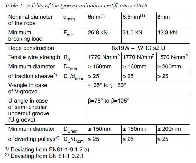
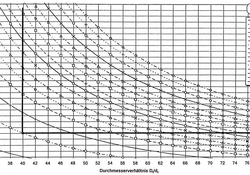
Where the rope section exposed to the highest level of stress travels over the traction sheave and two deflecting pulleys (with the bending length determined on the safe side corresponding to two distances between storeys), the anticipated number of trips can be estimated for different diameter ratios D/d and safety factors- Sf in accordance with available graphs, whereby “single variety D/d” and different D/d ratios for the traction and deflecting pulley were taken into consideration. Intermediate values can be interpolated using a provided method. Finally, the range of validity of the type testing certificate G515 is summarized in Table 1.
6. Plastic Diverting Pulleys
The product type test certificate G515 is valid for steel diverting pulleys or cast and plastic pulleys. The advantages of plastic diverting pulleys are to be found in the low weight and the assembly. Furthermore, the lifetime is longer when steel wire ropes run over plastic pulleys is longer than when they run over a steel pulley of the same diameter. However, the detection of the replacement state of wear can be made more difficult when using plastic pulleys due to externally visible wire breaks at reference lengths. All in all, there is no doubt concerning a reliable detection of a replacement state of wear as running over the traction sheave with form grooves results in the rope being subjected to externally visible wire breaks. An interesting aspect despite this is the influence which the plastic diverting pulleys have on the pulleys which are rolled over in the friction driven lift. Fatigue bending tests have been carried out for this purpose, during which the zone which is subjected to the highest load always runs over the diverting pulley and the friction pulley. Comparative tests have been carried out with steel diverting pulleys and plastic ones, each of them being combined with the steel friction pulley. The diverting pulley was additionally tested with a pulley to rope diameter ratio of DU/dnom=40 and DU/dnom=25. A result of the fatigue bending tests was that the wire break development is slightly slowed down when using plastic diverting pulleys, when compared to steel diverting pulleys. The combination steel friction pulley/steel deflecting pulley, the replacement state of wear was arrived at earlier than was the case with the combination steel friction pulley/plastic pulley. The tests were continued with after the replacement of state of wear had been reached and it was then aborted at a bending cycle of N = 2 million. The period between achieving the replacement state of wear and the abortion of the tests resulted in a number of bending cycles being achieved which correspond to a minimum of 3 lift years for a strongly frequented system. The ropes had not broken at that moment in time. The test ropes which were used for the subsequent tensile test in order to determine the residual breaking force were cast on both sides. During the tensile tests, the bending zone was in the centre of the free test length. The calculated real bending forces of the used ropes still come close to reaching the minimum bending force when the rope is n a new condition.
7. Conclusion
The use of thin ropes in friction driven lifts normally means bypassing the requirements of EN81-1. However, this cannot sacrifice the safety of the users. Extensive additional measures will furnish proof of the equivalence of the new solution with the requirements of the standards, in addition to a notified body being documented in the product type test certificates. Cost-optimized drives are also possible for poorly and moderately frequented friction pulley lifts. A cost reduction on the drive side always goes hand in hand with a reduction of the pulley to rope ratio D/d. This reduction is restricted by the requirements of EN 81-1. The product type test certificate G515 from Pfeifer DRAKO and the additional measures which are formulated in it is supported in safety times, opening up the way for systems with practically any form of friction pulley, diameter ratios of D/d ≥ 25 and rope safety factors which deviate from the calculation methods in EN 81-1, Annex N. The choice of either steel or plastic diverting pulleys hereby has no effect on the detection of the replacement state of wear of the steel wire ropes concerned.
References
Feyrer, K. (2002). Drahtseile. Springer Verlag Berlin 2002
Get more of Elevator World. Sign up for our free e-newsletter.
