Smart Step Measures Escalators’ Heartbeats
Sep 1, 2020
A study on the smart step, a data gathering device for escalators
by Dr. Ali Albadri
This article is a study showing the type and category of data we at Tube Lines Specialist Services obtained from our “smart step” invention. Though it was explained in 2008,[1] no other publication since has been made on it. The traces of the data from the step are systematic, consistent, repeatable and reliable. They can support many areas in the escalator industry, such as design, maintenance, refurbishment and asset management. Our hope is that this article will open a new chapter in studying the behavior and pattern of escalator operation and maintenance.
We have been using the smart step as a vital and critical tool in maintenance. We also have used it to check and verify the quality of newly installed escalators. The smart step has also been used as a detection tool to, for example, determine the impact of ground movements on escalator structural integrity during major ground (civil) works near escalators.
The smart step measures and monitors the mechanical and structural integrity of escalators. It is fair to say that there are no similar devices; therefore, there is a severe lack of associated technical references. However, an upcoming article will give exposure to the type and quality of signals and data traces from which the escalator industry could benefit. This article will detail the quality of information the smart step can provide designers and maintenance companies.
What the Smart Step Is
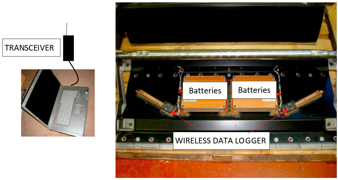
The smart step is a conventional escalator step (Figure 1) equipped with a variety of sensor types and communication devices. Sensors like strain gauges, vibration sensors, proximity sensors, laser sensors and deflection sensors are mounted throughout the step. The battery-powered storage and communication system transmits the data wirelessly to the surrounding area of the escalator. This area has a 15-m local radius, and further locations can be reached via the internet.
In this study, a smart step was built to run a newly fully refurbished escalator. Eight strain gauges were mounted throughout the step (Figure 1). The gauges were located at critical locations in the step. These locations were determined via finite element analysis with a 3D model of the step. The model was tested by doing axial, torsion and chain differential tests per the setups specified in the BS EN 115 standard. The idea of this study is to collect and study baseline data/traces from the smart step, which are collected from running the step in an unloaded (passenger-less) escalator.
Results and Discussion
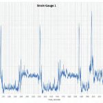
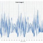
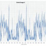
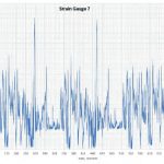
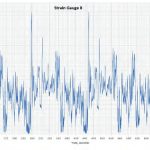
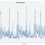
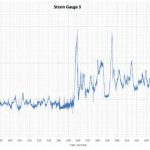
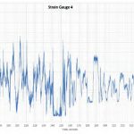
Figure 2 shows data of traces for nine strain gauges, which were wirelessly downloaded from the smart step to a computer after running the escalator for more than 15 min. Strain Gauge 2 developed a malfunction; therefore, its data have been ignored.
The systematic, consistent and repeatable behavior of the traces when the step was run on the main side (passenger side) and return side (non-passenger side) of the escalator can be quickly recognized from the data in Figure 2. Each complete step revolution in the escalator is well-defined and recognized. Although the traces are dependent on the specific locations of the gauges mounted in the step, the data/traces give fingerprints to the nature and quality of the path that the step is passing through in the escalator. The traces clearly show the regions of high and low stresses to which a step in the step band is subjected while running in the escalator. It can be deduced that the data from the smart step truly reflect occurrences inside the escalator.
In-depth looks into each individual cycle in Figure 2, into each trace from each strain gauge, give great information about the nature of interaction between the smart step and many other escalator components and subassemblies, such as tracks, return “D”s, brackets and carriage. Figure 2 shows that each trace consists of positive and negative stress levels. The positive level suggests the location in the step is subjected to tension, while the negative level suggests the location is subjected to compression. The high or low values of those stresses depend on the escalator build quality, such as how well the tracks and “D”s are aligned and leveled, whether any are loose or out of level in the brackets that support the tracks and whether there is physical contact between the step band and side skirtings. This can be easily seen in the data and made more obvious if the events in the traces are compared to a sound coming from the machine or to visible scratches on the side skirting panels.
The locations of the events and measurements in the traces can be easily traced back to the path of the step in the escalator via simple hand calculations — that is, by knowing the speed and height of the escalator. The length of the escalator can be calculated from the height. Alternatively, the locations of these events can be defined by mounting an electronic marker (such as a proximity sensor) in the step to define the beginning and end of each cycle.
Conclusions
This study shows the advantages an invention like the smart step can give escalator designers and maintainers. The traces from the step show the consistency and reliability of the data. They show distinct features for each location in the step or in the step band on one side and in the entire escalator on another side. The systematic repeat of the cycles and the clear distinction in each trace when the smart step is on the passenger or return (non-passenger) side give a lot of information about what is going on inside the escalator. That information includes:
- Quality and alignment of tracks and “D”s
- Alignment and rigidity of the brackets that carry the tracks and “D”s
- Loose connections
- Quality of the carriage and whether it is functioning correctly
- Alignment and quality of loading relieving ramps
- Quality of chain and whether there is a chain differential
- Quality and alignment of step band
- Quality and strength of step design
- External mechanical impacts with other parts of the escalator, such as the combplates/sections or skirting.
The smart step can be treated as the black box for the escalator. It records existing and historical events, providing benefits to the asset management company, especially during interventions. It can be used as a tool for the following purposes:
- Verification of the escalator’s design and strength
- Obtainment of real data for prioritizing maintenance schedules
- Investigating incidents/special events
- Monitoring the escalator’s structural integrity during civil projects that could cause ground movements near the escalator.
- Improving and developing many escalator components and subassemblies
- Predicating the fatigue life of the escalator’s mechanical components
- Strain Gauge 1
- Strain Gauge 3
- Strain Gauge 4
- Strain Gauge 4
- Strain Gauge 6
- Strain Gauge 7
- Strain Gauge 8
- Strain Gauge 9
- Strain Gauge 10 / Figure 2: The full spectrum of measurements recorded by the strain gauges from the smart step
- Strain Gauge 1
- Strain Gauge 3
- Strain Gauge 4
- Strain Gauge 5
- Strain Gauge 6
- Strain Gauge 7
- Strain Gauge 8
- Strain Gauge 9
- Strain Gauge 10 / Figure 3: The plots of one cycle trace from the traces of the strain gauges in Figure 2
References
[1] Dr. Ali Albadri. “Tube Lines Gets Smart to Monitor Escalator Wear,”
Computer Weekly (January 7, 2008).
Get more of Elevator World. Sign up for our free e-newsletter.
