by Serdar Tavaslıoğlu
MRL elevators are relatively new systems among elevator applications. With the “A-2 April 2007” addition of the article “6. Machinery and pulley spaces” to TS EN 81-1 standard, MRL systems have been adopted to the code. With this amendment, safety requirements are defined under the title “6.4 Machinery inside the well” and this clause has been updated as 5.2.6.4 in TS EN 81-20. Although the machinery is placed in the headroom in general practice, the same clause points out the safety requirements for placing the machinery on platforms at the bottom or in the middle of the well. In this article, we will dwell on machinery placement in the headroom.
Placing the elevator machinery in the well certainly offers many architectural benefits. Benefits such as the absence of a machine room and the requirements related to it, such as access, lighting and ventilation holes, saving of space and costs are attractive for the building designers. Additionally, being a brand-new type, it offers some technological development and a gets fashionable. However, safety requirements should not be neglected — otherwise, the section can be highly insecure. The issues that should be considered are:
A. Access to the machine, leaving the machinery space and working space,
B. Car suspension types,
C. Installation of the machinery in the well,
D. Placement of the control devices.
For the implementations within the well, implementing a system that evaluates the risks and takes safety precautions do not cause any problems. Making implementations without performing the necessary strength calculations as well as without neglecting the risks may be dangerous. They cannot be performed through ear fullness. The ones who implement the system should be careful like the ones who wants such an implementation. Now, I will review the conditions that should be met and then I will propose another method that is safer and accepted by the standard.
A. Access to the Machine, Leaving Machinery Space and the Working Space
The places where the machinery or machines are located in the well should be safely and easily accessible with a platform that has fulfilled the necessary conditions or from the top of car. Under all circumstances, the height of these access routes should not be less than 1.80 m and sufficient lighting should be provided. For this, a height of at least 2.10 m, a horizontal working area of 0.5 to 0.6 m in front of the machine, at least 0.5 m width in front of the control panels, and 0.7 m depth must be required. In addition, the unprotected rotating parts of the machines must have a vertical distance of at least 0.3 m above them. These requirements are defined in TS EN 81-20 of the clause 5.2.6.4.2.1.
The use of the car top as a working area also obliges it to be made safe and to leave it safely. In the standard clause 5.2.6.4.3, it is stated that the slippage or fall of the car must be prevented by a mechanical locking device in the car against the occurrence of uncontrolled or unexpected movement during maintenance or control while on the car. This device must also be controlled by an electrical safety device. The systems generally used are to fix the brother with a one-sided device and to ensure that it is trapped on the rails by hanging the car unevenly in case of uncontrolled movement. This system is not a suspension system, so it is not necessary to make two pieces of reciprocal space. Since a balanced suspension will occur if two pieces are used, there is no compression in the car and it is necessary to mechanically calculate that the system can carry the car and load. If the necessary calculations are not made, the double system may become a more insecure system than the single system.
This device must be activated when working on the car. There may also be problems with the operation of the double system in the well, jamming of the car mechanisms may occur at the slightest movement. In the event of locking and jamming, it must be ensured that persons above the car leave the work area safely. This condition is specified in paragraph c of Article 5.2.6.4.3. Three options are specified in the relevant clause to satisfy this requirement.
- “via the landing door by a clear opening of at least 0,50 m x 0,70 m above the car door header / door drive, or
- via the car by access through an emergency trap door in the car roof according
- via an emergency door as 5.2.3.”
Obtaining a clearance of 0,5 x 0,7 between the top of the car door mechanism and the landing door frame may not always be possible. In order to obtain this clearance, motor or the machine should be placed at lower levels. Instead, placing an emergency trap door is an easier and more practical method because it is difficult to place emergency tap door over the well in existing MRL elevators. It should be considered while placing order for cabins to these elevators. It should be a part of design otherwise finding a solution gets harder.
In fact, another requirement may be added. In the case of adjacent cars, the distance between the top of an elevator with the top of the other elevator may be 35 cm or if this distance is longer a portable bridge with handrails and with a width of 50 cm should be used on the well. This distance cannot be more than 1 m. (TS EN 81-20 5.4.6.2) In the event that the other options cannot be used, it is possible to leave the workplace safely by fulfilling the requirements of clause 5.4.6.2. It should be noted that the partition consoles between the two elevators and the last floor separator, if any, should be placed accordingly.
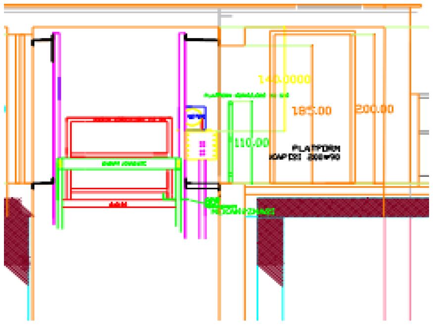
As shown in Figure 1, in a “adjacent elevator,” car balustrade and the well separator, if available, should be openable and the well of the compartment profile of the caret for security where it is locked from the top of the car +/- 50 cm vertical height does not exceed one needs to be installed on the ground (Article 5.2.6.4.5.3 c).
In the case that the distance between two cars is more than 35 cm, place with a platform to be added clearance distances secure can be made for a separate hyperlink or even without pin the working area it will be possible to safely leave. The edges of the platform should be at a sufficient distance from the car projection. At the point where the car is mechanically locked, two elevators also cubicle over easily accessible, a switch that will bring the two cars to the same level and take the elevators to the maintenance control (button) putting it in makes the evacuation process risk-free. The lifts should not return to normal operation without reset at the control panel done. The work of juxtaposing the two elevators and safe evacuation should also be added to rescue operating training. This must be indicated in writing in the instruction manual and in the rescue operation instruction. This method may provide an application convenience in some cases.
B. Car Suspension Shapes
In MRL elevators, pulley systems are generally used. In systems with top pulleys, quite high headrooms are required because the car should not pass over the machine level. In addition, in the top-pulley system, a larger drive pulley is required to provide the distance between the car and the counterweight pulleys, which increases the cost. Therefore, it is generally preferred to use systems which are placed below or at the sides. There are two options that can be preferred. Guide rails can be placed at the front or at the back based on the suspension line.
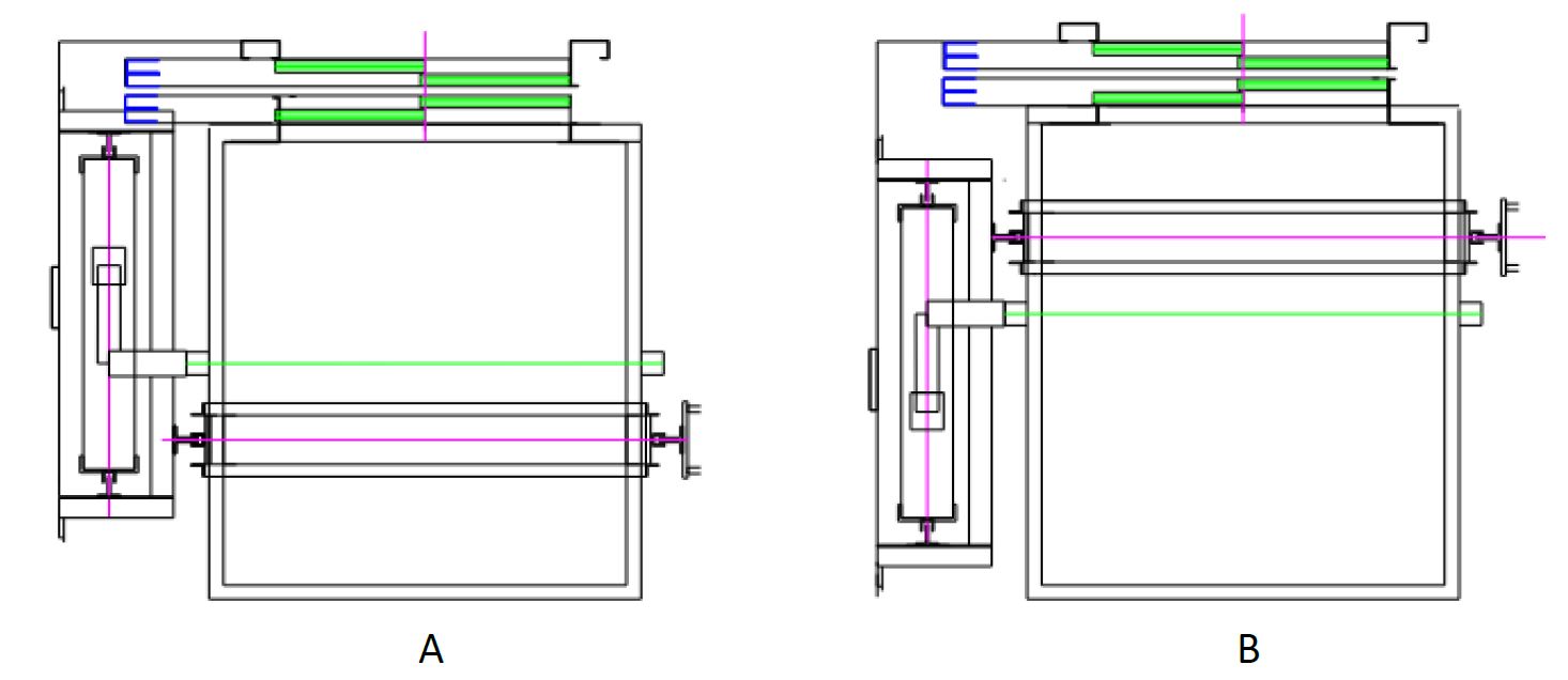
Two different applications are shown in Figure 2 A and B drawings. In the drawing A, car frame is at the back and considering that the door and the frame balance each other, the suspension axis (green line) is brought to the center of the car. As the car is suspended from its gravity center, it provides a comfortable ride. However, in the safety gear, there will be an adhesion on the rail axle (red line) , since the door, car’s center of gravity and pulleys will be in front of the rail axle, occurred forces will try to bend the the frame. Therefore, in such applications, suspensions for the car from the frame and also connections to the car should be made and it should be checked that the car frame and bolt connections are resistant to such a bending in the X direction. In Figure B, the car frame is moved to the front, therefore the center of gravity is quite prominent due to the car door and frame. Car total center of gravity (frame, car, door etc.), rail axle with suspension axle (red line with green line) between is placed so that (in terms of comfort, being closer to the green line is recommended). This ensures a stabilization in normal operation, as well as prevents the formation of large bending forces in the frame during braking. In this application, there is no need for car suspension lamas. Considering that the strength calculations are also made and that it is safe, when we examine the drawings:
- In Figure 2 A, the weight frame and the door mechanism panels collide. To correct this, either the door must be set off or the frame must be pulled back further. Figure 2 B is appropriate in this respect. Since the weight frame is behind, it offers a comfortable application.
- Long machine (sausage) application is difficult because the machine is placed on the door side in Figure 2 A. Getting on the door mechanisms is required. In Figure 2 B, the there is a convenient distance because the machine is placed on the side of the well, so the desired type of machine application will be easy. (The machine should not be at the top of the rail, and car can pass above the machine if necessary.)
- In Figure 2 A, constructing the required working areas for the motor defined in Clause 5.2.6.4.2.1 of TS EN 81-20 may only be possible in large cars. Constructing a 0,5 x 0,6 place between the door mechanism and frame may not always be possible. Additionally, since, the frame, buffers and skirt sheet at the pit will remain by the door of the well, sufficient safety spaces can be easily created at the back. Even in medium-sized elevators, Article 5.2.5.8.1 Schedule 4 Type 3 Posture position can be provided.
- Trap doors, which are often required in MRL elevators, on the car present difficulties in Figure 2 A but having a trap door will be easier in Figure 2 B due to the large landing.
- Placing the remote-controlled regulators close to the door in Figure 2 B is a convenience. It provides great convenience for the inspection and maintenance. For Figure 2 A, placing the regulator near the door has additional workings.
- In case of there are two elevators next to each other, Figure 2 B allows evacuation from the top of the car. Figure 2 A is more difficult to implement due to the door mechanisms and rope path.
Because of such kind of features, the method used in Figure 2 B is recommended as its benefits are more than the other. On the other hand, if the required precautions are taken, then Figure 2 A is also unobjectionable. Here, only convenience is considered.

C. Installation of Machine in the Well
The pedestals to which elevator machines are connected must have sufficient strength against the forces and stresses that will occur in various operating situations. Strength calculations are made by taking into account the braking conditions up and down this base to which the drive group is connected. The same calculations should also be done for the connection types of this pedestal. For the pedestals in the well, two connection forms are generally used. The pedestal must be attached either to the wall or to the rails. In order to be more robust, the connections made to both the wall and the rails do not form such a solid structure, contrary to what is expected. The movements consisting of the extention of the due to the temperature in the well and the dragging of the concrete are movements in different directions. Due to the heat in the rails, elongation and shortening move the fixed concrete joints up and down and loosen them over time and unwanted connection errors may occur. Therefore, it is undesirable in mechanics to connect materials that behave differently.
The safety coefficient of mechanical connection for connections to the wall should be considered as “8.” (Article 4.1.2.5 of Annex 1 to the Machinery Safety Regulation and 6.1.1.) The total load acting on the machine base ((P+Q)/2 + (G+H)) ( The full car is at the top, the car side is connected to the end of the rope on the other rail, The counterweight is at the bottom, the rope and the counterweight are all connected to the machine base) should be calculated taking into account the upward braking situation. The force contained here must be 8 times safer, i.e., 8 times smaller than the cutting load of the total bolts connected to the wall. The connecting dowels (Fatigue) attached to the wall must be certified. In other words, chemical dowel resistant to vibrations should be used. Mechanical jacketed dowels are fixing dowels that are not resistant to vibrations and become loose over time due to machine vibrations. These connections are not considered secure.
If the connection point is the rails, it should be taken into account that the load mentioned above ((P+Q)/2 + (G+H)) will be shared between the rails to which the pedestal is connected for upwards braking according to the connection form of the machine-machine base (k1=2). Additionally, the additional load must also be taken into account when making rail calculations.

The value which is defined as Maux,in buckling stress formula is the force due to additional loads attached to the rails and k3 coefficient is its impact factor.
If you take an upwards safety stop from the car, this part should be considered. The k3 value is used when the machine brake is used for the upwards safety stop. (TS EN 81-20 article 5.7.4.4) If this calculation is done correctly, it will not be the right choice to use weight guide rails in cases where console connections are not made very often on the rails carrying the pedestal.
In machine pedestal connections, the brackets are not considered to be stabilizer connections. Because although the brackets hold the rail against lateral movements, they are designed to allow the vertical thermal movements of the rail. However, as specified in TS EN 81-20 article 5.7.2.3.5, brackets have a tension value. This calculation is made consecutively, and it is allowed if the tension force of the consecutive brackets is greater than 8 times of the force coming to the machine base. In case of non-calculation, the cutting forces should be calculated by drilling the pedestals and rails and the connections should be made fixed with bolts.
In well interior applications, it is necessary to comply with the isolation rules exactly as in the machine room applications. This is not a comfort problem, but a problem that directly concerns building safety.
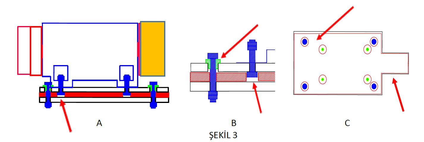
Machines of 3 KW and above pose a threat to building resonance frequencies due to the harmonics they produce, so they must be isolated from the building. Placing insulation material between two plates does not mean that insulation is made. Contact of two plates metallic must also be blocked. These frequencies are the same electrical current they switch from metal contacts to other metals, and they spread. They spoil the comfort of both the building and the elevator, as well as threatening building safety. Therefore, the connection points of both plates being isolated from each other. The machine must be directly connected to the upper plate, and must have connection and contact with the lower plate (Figure 3 A and B).
The upper plate must be attached to the lower plate, and the upper plate must be connected to the connection bolt with the help of an insulating material (Figure 3 B, green colored insulation cap). To prevent the machine from tilting forward plates it should be extended towards the side of the rope, the bottom plate connections (red and blue) machine against lateral movements of the machine top plate of connections (red and green) must be connected from outside (Figure 3 C).
D. Placement of Control Devices
Since MRL elevators do not have a machine room, the placement of control panels is a problem.
a. Because it can’t see the elevator movements,
b. To ensure that tests can be carried out from outside the well,
c. To prevent interference from all,
d. In order to use the main cutter switch and other fuses, it is necessary to take additional safety measures.
However, the place where these panels are placed is practically the last floor of the door edge, the inside of the door frame edge or the well wall. In the application of corridor used in the apartments on the last floor, unwanted situations occur during maintenance, malfunction and control. Just as panel noises create a discomfort, crowded and inevitable elevator oil pollution are not very desirable images for a modern application. The problems created by the fact that these works are carried out in the presence of the residents of the last floor apartment may be the subject of a separate article. There are tragi-comic situations in the elevator work with children, curious elderly, protective and anxious mothers. Another problem is the lack of a separate area for storing the oil, top, logbook, electrical drawings of the elevator. The prolongation of the distance between the control system and the machine is undesirable in terms of communication and machine supply.
Suggestion
I’m not against MRL elevators, but I’m only in favor of using them in cases where the machine room application cannot be done. Because, as we mentioned above, apart from their advantages, they also bring up many risks with them. Apart from the risks mentioned here, it is necessary to take into account the risks that occur in situations such as overhaul, machine-rope replacement, pulley replacement. In the event of a natural disaster such as any fire or earthquake, not being able to directly intervene in the machine and rescue in the car is a problem in itself. That’s why I’m in favor of platform work on MRL elevators.
Elevators used in new buildings are generally required over 1.50 m/s speed. In these elevators, although the top floor height of the well is required to be 4.20 m as standard, 4.50 m top layer height is left in comfortable applications. Assuming that the floor heights are generally 3.00 meters, it brings up an inevitable elevation of 1.50 meters on the roof. With a small correction in this regard, it is possible to make many problems easier. The additional cost in this regard will be to increase the height of 1.50 m to 2.10 m only in the attic. Raising the well top by 60 cm and a closed corridor of 1.2-1.5 m width to be built next to a censor well can solve many problems.
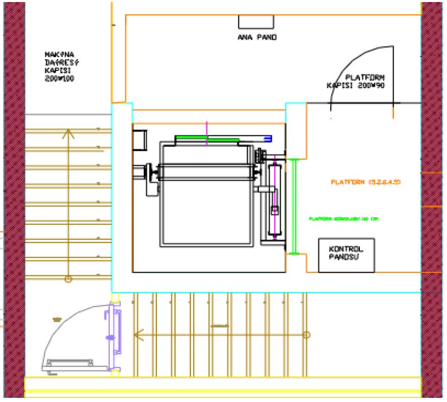
In the building with the drawing on the side (Figure 4) an MRL application was performed. But the height on the roof is 1.50 m instead of 2.10 m and a closed corridor was added to its side. A lockable door was placed in this closed corridor and the well wall on the side of the corridor where the machine base was placed was opened. In front of this opening, a balustrade at a height of 1.10 m in accordance with the shape defined in the Standard was placed and necessary security was provided. Thus, it has a door that opens to the outside and is 200 x 90 cm wide and can be locked and fired of concrete, stationary, machine ve directly accessing the regulator a platform has been obtained. Since it has a height of 2.10 m and a working area of 0.5×0.6 m and provides the desired dimensions in front of the panel, it has the platform features required by the standard. (TS EN 81-20 Article 5.2.6.4.5)
The additional costs of this application are negligible. The machine was put in the same place again, and the rope lengths and counterweight rails remained the same. Only the main guiderails are elongated by 60 cm and connected to the upper beams. In addition, a locked door of non-combustible material was placed at the entrance of the corridor and a balustrade was put on the agenda. The lighting and sockets to be used here were already costs to be made on the well. Other than that, there is no cost. But for MRL elevator supplement a volume has been created and many risks have been eliminated. This system does not require the use of a car mechanical locking system or special panel with emergency cover application or test systems. Buddha brought supplement it is a situation that more than covers the costs.
In this form of application, if the height of the machine room is brought to the normal elevation it should be, it is also possible for the elevator to rise to the roof, it will only have to be properly raised on its platform. In buildings where there is a use of the attic, this application provides a great advantage.
If we examine the advantages of this system:
- Since it has a platform with locked space, the control systems do not need to stand in the middle. They does not need to be in the control board of the test equipment or the main table because panel sees the elevator from the middle. A locked and secure area has been created where normal boards will be placed. The distances in between are suitable for communication and feedings.
- There is no need for a remote-controlled regulator or a remote-controlled rescue device, as the machine and regulator can be directly intervened. Normal elevator systems are sufficient.
- Special evacuation systems are not needed in the elevator. Since the machine can be treated from the platform, there is no need for a cab mechanical locking system or emergency covers for evacuation. If necessary, it is easy to switch from the cab to the platform.
- As the machine can be mounted on the platform, the assembly of the machine and the base of the elevator is easy. The chain hoist is comfortable to use as there will be a distance above the motor. Likewise, malfunctions such as revision, rope replacement, pulley replacement can be easily made.
- Since the gaps on the car top have increased a lot, safety volumes can be easily created, and safety is more easily provided. Elevator maintenance can be done more safely.
- The elevator is safer because the works such as fault maintenance and control will not be done around. Moreover, there is a more comfortable application as noise and pollution are removed from general areas.
- An area has been created where the materials of the elevator, oil and top, the registry can be easily stored.
Conclusion
Providing a machine room for machine room-less elevators can be a practice that will relieve both users, installers and later maintainers in many respects (MR for MRL elevators). Many risks that I mentioned above are eliminated. Again, many applications become easier. It poses as much risk as a normal elevator as it has a locked door, but a second barrier with a high-opening device for children can still be placed in front of the balustrade. Apart from the method suggested here, other applications can be developed, but it should not be forgotten that the standard conditions must be met. Considering the advantages and cost reductions it brings, I think it is an application method that should be emphasized and I believe you will see many benefits. If it can be done, first MR, if not, then MRL, but meeting the necessary conditions should be provided as a definite condition. I wish everyone the best.
Get more of Elevator World. Sign up for our free e-newsletter.

