Steel Wire Rope
Jul 1, 2015

Thoughts on the ASME A17.6 standard for elevator suspension systems and corresponding A17.1/B44 requirements
by Louis Bialy, Miles P. Lamb and Martin Rhiner
Steel wire rope (SWR) has been used for many years as a major element in the elevator industry. Indeed, SWR has been applied for the suspension of elevators, as well as in compensation systems and as an important part of speed-governor systems. A wide range of SWRs has emerged, and many different configurations are in use. Some of the more common varieties of SWRs include left and right regular and Lang lay construction, using preformed and non-preformed arrangements. SWRs can be constructed of many different types of wire material, ranging from iron to high-tensile steel, including variations with corrosion-resistant properties. Strand constructions such as Warrington, Seale and filler are in common use, and various core materials such as natural and synthetic fiber, as well as independent wire rope, are also evident. SWRs with nominal Imperial dimensions, as well as metric varieties, are also deployed in North America and other parts of the world.
Around 2000, it was recognized that, despite the use of SWRs for many years, there was relatively little specificity in the ASME A17.1/CSA B44 code relating to SWRs. Moreover, new suspension-means technologies, such as aramid fiber ropes (AFRs) and non-circular elastomeric coated-steel suspension members, usually referred to as “coated steel belts” (CSBs), began to emerge. It became evident a standard that could be used to ensure the safe application of these technologies would be helpful. In support of this, the A17 Standards Committee embarked on a comprehensive standard intended to cover major suspension means in current use and provide for the inclusion of new technologies. The A17.6 standard that emerged as a result of this effort included strength and material requirements, as well as criteria for application, testing, inspection, replacement, identification and ordering SWRs, AFRs and CSBs.
Corresponding A17.1/B44 code changes were also developed to accommodate the A17.6 suspension-means standard. Comprehensive testing, inspection and replacement criteria were developed for all suspension means. Requirements for compensation means and governor ropes were also developed, resulting in a state-of-the-art set of provisions being made available to the elevator industry.
Development of the Standard
In developing the standard, SWRs in current usage in North America and other parts of the world were studied at great length. The knowledge base of users with longstanding experience was drawn upon, and the counsel of the Wire Rope Technical Board (a group comprised of experts from wire-rope manufacturers) was sought on numerous occasions. The experience base of users in Europe and elsewhere 6-mm governor SWRs had been permitted for many years was also leveraged in developing proposals for A17.6.
In developing the requirements for AFRs and CSBs, as well as small-diameter SWRs (4-8 mm), extensive test results were studied, and the performance, reliability and durability of these elements were assessed. Visits to major laboratories, test facilities and factories that supported the development, testing and production of AFRs and CSBs were also undertaken in preparation of the A17.6 standard. The draft standard and corresponding A17.1/B44 code changes went through the rigorous approval process required by American Society of Mechanical Engineers (ASME) and American National Standards Institute, including the public-review process. Ultimately, A17.6-2010 and the corresponding A17.1/B44 requirements were published.
Around 2000, it was recognized that, despite the use of SWRs for many years, there was relatively little specificity in the ASME A17.1/CSA B44 code relating to SWRs.
A17.6 Part 1: Stranded Carbon SWRs
This part of the standard covers 4- to 38-mm SWRs for suspension and compensation. It describes preformed, non-preformed, fiber and steel core configurations and many different constructions and materials. Detailed inspection and replacement criteria are also provided. This part also covers six-, eight- and nine-strand rope designs. SWR sizes ≥ 6 mm for governor ropes are also addressed. Relevant ASME, ASTM International and International Organization for Standardization (ISO) standards relating to SWRs and their components are documented. The basic elements of a typical SWR are defined and illustrated in Figure 1.
Basic information relating to the function and positioning of wires are elaborated upon, including the layering of wires and the finish and quality of wire coating. Wire “level” or tensile strength “grades” for the wires in various SWR grades are defined.
The standard describes the construction of strands as illustrated in Figures 2-5. These may be “round” or “compacted round,” and of different “strand lay length” and lay direction. Parallel lay construction comprises at least two layers of wires, laid in the same direction, with all the wire layers having equal lay lengths. The wires of superimposed layers are arranged parallel to each other for linear contact between wires. The most common constructions of strand are Seale, Warrington and filler.
Part 1 of the standard also describes the most common SWR core materials in use. These are natural-fiber cores such as hemp or sisal, independent wire-rope cores and solid polymer cores (Figure 6).
Part 1 of A17.6 describes the construction and properties of SWRs in detail. SWR types in common use are single- and multi-layered with “round” and “compacted round” strands (Figure 7). SWR classification entails a description of the number and type of strands and the number of wires per strand, as well as strand construction and core material. The minimum breaking forces for various Imperial rope grades such as iron, traction, extra high strength, as well as corresponding metric rope grades, are summarized in Mandatory Appendix I. SWR lay (left or right, regular or Lang) and lay lengths are also described in the standard. Regular-lay SWRs are easily recognizable, as the alignment of the wires in the strands are axial, while the alignment of wires in Lang lay are transverse (Figure 8). Regular-lay SWRs typically exhibit less stretch than Lang lay SWRs, while Lang lay facilitates higher traction properties.
Part 1 of A17.6 also provides information on the properties, dimensional characteristics and tolerances of SWRs. Testing of SWRs and compliance with code requirements, as well as ordering, packaging and identification information are also provided. Replacement criteria in terms of crown and valley wire breaks, diameter reduction and evidence of rouging are fully addressed.
A17.6 Part 2: Aramid Fiber Ropes
This part of the standard covers general requirements for AFRs for suspension and compensation purposes. Relevant ASTM, ASME, ISO and other standards relating to the materials and test methods are identified. Fiber material and properties, load-carrying elements, rope cover material and mechanical properties are defined and described. Fiber tensile strength and percentage elongation requirements are specified. Much of the terminology is identical to that applicable to SWRs. Sizes, geometry and dimensional tolerances are also addressed.
AFRs of circular and non-circular cross-sections are included. Methodology for testing and means of ensuring compliance, including the required quality-control processes, are specified. Detailed replacement and life-limit criteria are provided in terms that must be capable of visual, mechanical or electronic inspection.
Replacements of AFRs are required to be the same as the original members. The whole set of suspension members are to be replaced if one member is damaged or unsuitable for use. AFR cover damage leading to wear or damage to load-carrying elements requires replacement of the whole set of members. Replacement is required if the fatigue life limit or internal abrasive wear limit of any member is reached. If the residual strength of any member is reduced to 60% of the code’s required original strength, all members must be replaced.
A17.6 Part 3: Non-Circular Elastomeric Coated Steel Suspension Members
This part of the standard covers general requirements for CSBs for suspension and compensation purposes. ASTM, ASME, ISO and other standards relating to the materials and test methods are identified. Much of the terminology is identical to that applicable to SWRs. The load-carrying elements are in the form of steel cords, each of which comprises steel strands helically laid around a central steel strand. The cords are arranged in parallel and molded within an elastomeric coating. The coating retains the cords in their respective positions and provides traction. The tractive force is transmitted to the cords. Sizes, geometry and dimensional tolerances are also addressed. Cord material and properties, elastomeric coating material and mechanical properties are defined and described. Wire, strand and cord construction, material and mechanical properties are specified. Methodology for testing and means of ensuring compliance, including the required quality control processes, are also specified.
Detailed replacement and life-limit criteria are provided in Part 3 of the standard. Replacements are to be the same as the original members, and whole sets are to be replaced. Replacement is required if breakage of a single CSB occurs or if coating damage exposing any strand of any cord to wear or damage, or any breakthrough of a load-carrying element occurs. Replacement of the entire set is also required if the fatigue life limit or internal abrasive wear limit is reached.
If the residual strength of any member is reduced to 60% of the code-required rated breaking force, all members must be replaced.
Corresponding A17.1/B44 Code Requirements
A17.6 is referenced in A17.1/B44. Specific requirements relating to suspension means in A17.1/B44 were developed to facilitate safe application of suspension, compensation and governor systems.
Factors of safety (FOSes) for SWRs, AFRs and CSBs are generally based on suspension-member speed. AFRs and CSBs have additional residual strength requirements of 60% of rated breaking force as a minimum. For governor SWRs with 6 < D < 9.5 mm, the FOS is ≥ 8, while for SWRs with D ≥ 9.5 mm, the FOS is ≥ 5. It should be noted that the smaller-diameter SWRs require higher FOSes.
All traction elevators require traction-loss detection means, which detect relative motion between the suspension means and driving sheave. If traction is lost, power is removed from the driving machine’s motor and brake. Manual reset is required using a Group 1 key. The means is required to be tested per specific procedures described in the code, and maintenance criteria for the traction-loss means are to be included in the maintenance control program (MCP).
Two forms of engineering tests are required for AFRs, CSBs and small-diameter (4-8 mm) SWRs. The first test is for the member slipping at inspection speed on the sheave with tension corresponding to maximum capacity. The member passes this test if it survives for 4 min. under this condition.
The second engineering test requires three successive tests (at approximately the same portion of member) under emergency stopping conditions at rated speed with tension corresponding to maximum capacity. The member passes if it does not sustain damage that would require replacement.
In addition, elevators equipped with AFRs, CSBs and small-diameter (4-8 mm) SWRs require means to detect a broken suspension member that will stop the elevator at a controlled rate at the next landing for which a demand was registered and not restart until manually reset. Elevators equipped with SWRs in the range of 8-9.5 mm also require broken suspension member detection means unless they have an FOS not less than 12. It is further required that elevators equipped with AFRs and CSBs have a residual-strength detection means that will operate before any suspension member is reduced in strength to 60% of its rated breaking force, and stop the elevator at the next available landing and not restart until manually reset. Both the broken suspension and residual strength means are required to be tested per specific procedures described in the code, and maintenance criteria for these means are to be included in the MCP.
Concluding Remarks
The A17.6 standard and corresponding A17.1/B44 code requirements represent the state of the art in elevator suspension-means requirements applicable in many parts of the world. As new technologies become established, they will be added to the A17.6 standard, and corresponding requirements will be considered for inclusion in A17.1/B44.
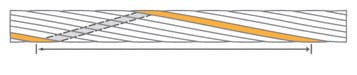
Figure 2: Strand lay length 
Figure 3: (l-r) “Round” and “compacted round” strands 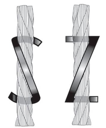
Figure 4: (l-r) Left and right lay strands 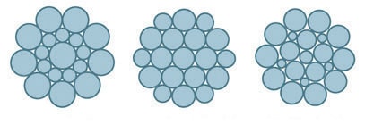
Figure 5: Common strand constructions 
Figure 6: (l-r) Natural fiber, independent wire rope and polymer cores 
Figure 7: (l-r) Single-layered, compacted outer strand and multi-layered SWRs 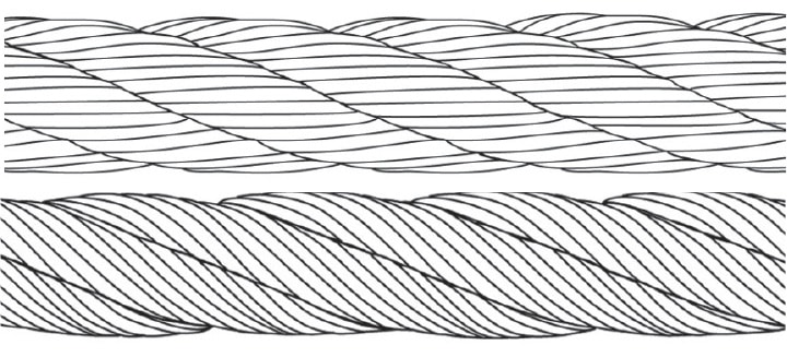
Figure 8: Regular lay (above) and Lang lay (below) 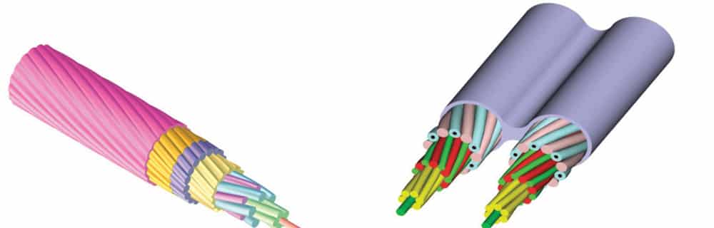
Figure 9: Representations of AFRs showing “circular” and “non-circular” configurations. The outer rope cover provides traction. The load-carrying filaments are protected by elastomeric or other suitable material. 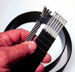
Figure 10: CSB showing cords and coating, and an SWR for comparison
Get more of Elevator World. Sign up for our free e-newsletter.


