Submersible Electric Motors for Hydraulic Lifts
Mar 1, 2012
Choosing the appropriate motor for an elevator can allow more efficient energy use.
by Ivo Busi and Fabio Calegari
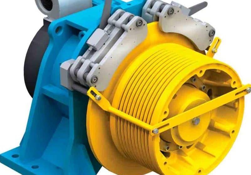
In recent years, the hydraulic lift, as an alternative to the electric traction lift, has become one of the simplest and most common elevator applications in use. Its operational principle is based on a piston driven by hydraulic oil provided by pressure from a power pump. The system’s core consists of an electric motor, which defines system performance and transmits high power with actuation accuracy. The most common configuration sees the motor completely submerged in oil inside the tank and directly connected to a pump – usually a screw pump. Consequently, no other space outside the tank is utilized. Motor efficiency and size influence elevator performance. For this reason, choosing the correct motor and system size for its intended use is important.
Energy is proportional to car speed and hydraulic elevators do not use energy for downward travel. Thus, hydraulic elevators are useful for controlling average travel speed without additional cost by simply acting on the downward travel speed (increasing speed) and upward travel speed (decreasing speed). Using this technique while maintaining an average (upward/downward) speed equal to rated speed, a smaller motor can be used, which can reduce energy consumption by 20-30%. Choosing the appropriate motor for an elevator can allow more efficient energy use.
Operational Conditions
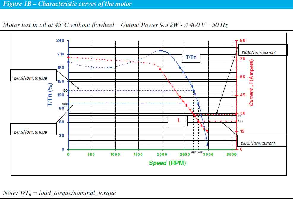
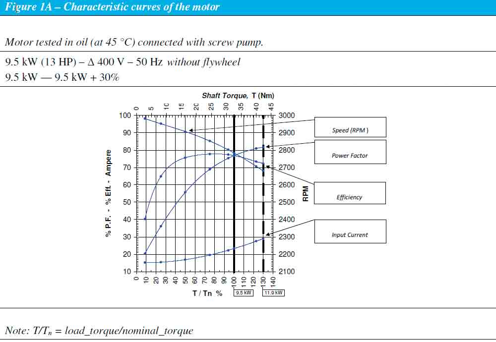
Generally, an elevator does not operate at full load for each travel. For this reason, it is possible to reduce motor losses by selecting a motor 20% smaller than the design value and overloading it during full load conditions (Figure 1A and Figure 1B). However, it is necessary to verify the motor can bear the overload (Figures 1A, 1B and 2), both in terms of output torque and overheating.
Overload
The overload capacity of submersible motors is significant for both their construction characteristics and “open-type” construction, which allows optimum cooling conditions. Note that hydraulic oil has a heat transmission capacity greater than air (e.g., conventionally), which is more than 10 times higher, and also acts as an optimum electric insulator with dielectric strength more than three times greater than air. Today’s motors can support “guaranteed” overload torques with hot oil at 45°C (e.g., by 130% [T/Tn=1.3] per maximum 45 s by 145% [T/Tn-1.45] per maximum 15 s). Note, this is true for appropriate conditions only if the voltage and frequency are close to rated values (Figure 3).
However, the motor can provide its rated torque in both Zone A and Zone B, but could not fully satisfy its rated performance and shows deviations. Temperature increases could be higher than at rated voltage and frequency, with deviations and increases greater in Zone B than Zone A. It is recommended to not go beyond the border of Zone B (Figure 3). Generally, motors operate in paraffinic hydraulic oil (DIN 51524-1/2) with ISO VG 32-68 viscosity index and maximum oil temperatures of 70°C. If minimum temperature goes below 10°C, the use of oil heating devices is recommended. The maximum water content shall be less than 800 parts per million.
Soft Starter and VVVF
High-performance motors are designed according to IEC 60034-1 to support a periodic intermittent service by 40% (Type S4) or a type cycle such as S2 30 (Figure 4). To limit starting currents while avoiding current peaks in the transfer from a star-delta connection, a soft starter is often used, which continuously increases the voltage to keep the same level of current intensity.
Today, variable-voltage, variable-frequency (VVVF) inverters are designed for electrical drives for hydraulic lifts with a submersible motor. They are available in a closed-loop version with a position sensor on the motor for control in both upward and downward travel, and an open-loop version for upward control only.
Construction Peculiarities and Supply Conditions
Motor design is concerned with sizing, component shape and distance between components to increase product quality and reliability levels (Figure 5). For example, in electric-motor production, for hydraulic lifts to be generally connected to screw pumps, the utmost attention must be paid to the squareness between the flange and motor-shaft axis to get the motor-shaft axis aligned with the pump-shaft axis. During installation, elastic vibration absorbers, or dampers, are assembled to absorb already reduced motor vibrations. Because they are engineered for this application, current motors require less room at equal power and ensure low noise levels.
The Flywheel
The most common application provides for a flywheel to reduce deceleration peaks due to electric power interruptions and, in the case of stopping, improve comfort and stopping accuracy performance. The flywheel’s inertia is calculated from motor and system speed parameters. The flywheel’s friction in oil is accurately calculated and minimized to match various required parameters.
Installation and Maintenance
Current motor provisions include detailed instructions to ease installation and make system operation and maintenance safe. For example, transportation and handling are ensured by means of appropriate connections compliant with EN 81-2. The corrosion-resistant motor has an IP00 protection class and is equipped with integrated thermal protection in the form of Positive Temperature Coefficient (PTC) thermistor temperature sensors inserted into the windings and connected to the lift control panel. As the winding temperature rises, the PTC protection sensor activates a control circuit, which triggers a motor protection relay and shuts off motor power, protecting it from adverse overheating and burning.
Insulation System
An insulation system guaranteed for a submersible motor in oil/hydraulic fluid should be a minimum of thermal class “F” (155°C).
The Materials
Aside from using quality oil/hydraulic fluid, the choice of materials that form the motor’s insulation system are important. These carry out electric insulation and mechanical protection functions against undesired shocks and wear, must be chemically compatible. For example, interactions between enamel winding wires, impregnating resin and oil/hydraulic fluid are studied and verified by ad hoc-designed life tests.
Both construction and strategic process aspects are accurately considered to obtain high levels of motor quality and reliability, while also using supplementary components for electric insulation and mechanical protection. For example, two front protective coverings in a polymeric substance raise the reliability and quality of the insertion of copper-wire windings into the slots of the stator’s ferromagnetic core, protecting the enamel-insulated wire from the stator’s plates.
Stator Insulation
The insulation system of the wound stator is reinforced and optimized using resins suitable for multidip environmentally friendly impregnation processes with low-volatile organic-compound emissions containing no solvents. It also uses tubular sleevings for additional insulation and protection of wire/cable connection points and cables at the exit of the stator’s end-turn region.
Cable Protection
A braided tubular sleeving externally protects cables from undesired shocks and wear, which can occur during motor installation in small or narrow spaces, such as hydraulic power units and compact machine rooms. Plastic sleeving material shrinks and elongates while sliding in contact with surfaces, avoiding undesired shocks during motor transportation, installation or operation.
Tests and Certificates Tests
Today, quality submersible motors can be sold as free-pass products, provided the automatic commissioning procedures, both at the end of the production line on the finished motor and on strategic components during the production process, are optimized to ensure high reliability and safety levels. Strict automatic tests must be carried out prior to the impregnation process on every finished wound stator (strategically, the most important component) and, after the impregnation process, on every finished motor at the end of the production line.
Test Certificates
For each single motor produced (identified by a unique serial number), the manufacturer must provide a testing certificate certifying the execution, with positive result, of both verification tests required by the standards and regulations applicable to the product, and of the additional verification tests suggested by the experience and the “state of the art” to obtain high quality and reliability levels over time.
Summary
Key features in the use of in-oil submersible electric motors for lifts are summarized below:
Flexibility in the choice of system configuration
Possibility of operation with ecological fluid, per European environmental directives
- High reliability standards
- High travel comfort
- Low cost and reduced installation times
- Safety (also and mainly for seismic installations)
- Use, operation and maintenance savings (downward travel always occurs by gravity)
Get more of Elevator World. Sign up for our free e-newsletter.
