Suspension Means — Equalizing Loads to Extend Their Service Life
Oct 1, 2018

Hydraulic rope alignment systems substantially reduce rope wear on any elevator system.
This paper was presented at  Berlin 2018, the International Congress on Vertical Transportation Technologies, and first published in IAEE book Elevator Technology 22, edited by A. Lustig. It is a reprint with permission from the International Association of Elevator Engineers
  (www.elevcon.com).
In recent years, increasing problems have been identified with excessive wear of the suspension means on lifts, particularly on machine-room-less (MRL) systems. The causes are numerous, but the load distribution within the rope set is of great importance. According to Professor Klaus Feyrer’s well-known studies at the University of Stuttgart, the life of the entire rope set can be reduced by up to 40% if one rope deviates by only 15% from the average value of all the rope loads in the set. By utilizing a long-known physical principle, a device for permanent installation has been developed with which the rope loads can be compensated optimally without external energy supply (even during the lift’s travel) in new and existing installations. This article will deal with the operating principle, chosen design and results on selected elevators.
Introduction
Developments in the elevator market have led to today’s elevators losing validity of the time-honored estimate for the lifetime of a rope as being between 10 and 20 years — a lifetime that formerly was not achieved in cases of poor maintenance and/or assembly or extreme ambient conditions.
The demand for elevator systems with as small space requirements as possible is continuing unabated, the advantages for architects and building owners being highly apparent. These systems, which are generally designed as traction elevators without machine rooms, possess several special features with regards to their means of suspension:
- Multiple suspension (2:1 or higher)
- Low traction-sheave diameters
- Low rope diameters or belts, which permit as small a bending radii as possible
These features, which have been produced according to customers’ wishes, have negative effects on the lifetime of suspension means, when compared to direct-suspended elevator systems with rope diameters larger than 8 mm and large traction sheaves.
The multiple-suspension feature, for which the drive is frequently positioned directly in the shaft to save space, requires more deflection rollers. This means more bending points for the suspension means, generally also with counter-bending, which substantially increases the wear on steel ropes.
To reduce the required construction space even further, it is, of course, expedient to also reduce the diameters of the traction sheave and deflection rollers; at the same time, this permits application of inexpensive drives, which offer high speed but relatively low torque. Because the suspension means does not permit as small a bending radii as might be required — i.e., the ratio between the traction-sheave diameter and the suspension means diameter (D/d) cannot be too small — the diameters of the suspension means also have to be reduced. Therefore, rope diameters of approximately 6 mm can frequently be found in elevators without a machine room.
It is obvious that the smaller the rope diameter, the smaller the load capacity of these ropes will become, which means multiple ropes are then required (which substantially increases the possible bending capacity), or that ropes of a higher strength must be used so that the number of ropes required does not become too high. Such high-strength ropes demand greater traction-sheave hardness to minimize wear on these and on the ropes. Other solutions can be plastic-coated ropes, which, of course, cause hardly any or no wear on the traction sheaves but do cause other problems, such as in correctly determining discard criteria.
Without wishing to describe the individual relationships between the parameters in too much detail, it can be determined that a balanced mix must be found between the boundary conditions that does not excessively increase the wear on suspension means wherever space-saving elevator systems without machine rooms are required.
Ways to Reduce the Suspension-Means Wear
The above-mentioned design conditions for elevators without machine rooms all cause increased rope wear without possibility to compensate for the cause of this wear:
- Every deflection of the suspension ropes increases their wear.
- Counter-bending greatly increases the wear on the ropes.
- If the diameter ratio D/d is reduced linearly, rope wear increases exponentially.
- If the rope safety factor decreases linearly, rope wear also increases exponentially.
To compensate for factors detrimental to the rope life and yet continue to uphold a high running performance, all remaining ambient conditions for the suspension means must be optimally adapted in operation. In this way, the number of bending cycles can be increased once more.
Rope Maintenance
Almost all rope manufacturers offer an appropriate care agent for their steel ropes that reduces corrosion and abrasion. The ropes are pre-lubricated, but dust and abrasion can bind the lubricant so that the lubricating effect is continuously reduced.
Rope maintenance must be undertaken in accordance with the manufacturer’s recommendations to prevent unnecessary rope-life restrictions at this point, too.
Installation of New Suspensions
In part, rope manufacturers issue detailed instructions on how to install new ropes and what should always be observed in the interests of a long rope lifetime. In addition to rather obvious comments, such as that the ropes should not be kinked when laid, some manufacturers have also applied a marking on the ropes: the so-called eyeline or surface line. This line, applied in the suspension direction, makes it easy to ensure the ropes are not twisted when laid down during installation, a mistake that can occur very easily as the ropes start to twist by themselves. If, in spite of this, the ropes were to be laid twisted and then fastened onto the counterweight and cabin or in the shaft head in such a way they could no longer untwist, this would have severe negative effects on the lifetime, as additional and unnecessary wear would be taking place inside the rope during every elevator movement.
Load Distribution Between the Suspension Means
The above-mentioned twisting of the ropes also leads to load-capacity differences in the ropes during elevator movement, but this is only a small part of the problem. Far more serious, of course, is the actual adjustment of the ropes to each other.
The load distribution within the rope set is a decisive factor in the lifetime of the ropes. An equation is stated in the standard work on wire ropes in elevator construction by Dr. Klaus Feyrer.[1] By using this equation, the bending capacity of wire ropes can be determined, dependent on the rope tension. If all the parameters in this equation (ambient conditions, mechanical rope parameters, etc.) are kept the same, and only the difference in the rope tension is considered, astonishing effects of the load distribution on rope life are revealed. This has also been published by Pfeifer Drako in a technical document from November 23, 2009, based on the formula stated by Feyrer:
- A 5% reduction in load difference between the suspension ropes increases the lifetime by 11%.
- A 10% reduction in the load difference between the suspension ropes increases the lifetime by 23%.
- A 15% reduction in the load difference between the suspension ropes increases the lifetime by 38%.
Rope-tension measuring devices have been available on the market for some years now. In addition to the absolute cabin weight, using these devices can determine individual rope loads for adjustment. This is, of course, very useful, but still insufficient, as will be explained.
Varying Load Distribution During Travel
Naturally, it is only possible to adjust the ropes manually when the elevator system is at a standstill. This means that the position of the cabin in the shaft must be decided upon, and the ropes must be adjusted at this position. This generally means that, in the case of a 2:1 suspended system without a machine room, the cabin is positioned at the uppermost stop so that the end fastenings of the ropes can be reached for adjustment purposes.
Depending on the design of the rope-tension measuring devices, it may be possible to measure the progressions of the individual rope tensions in advance, during elevator movement, to determine the optimum setting of the ropes for subsequent adjustment. This is necessary, as the individual rope tensions constantly change during elevator movement, frequently to a substantial extent. Several factors can cause this: slight deviations between the grooves and ropes, out-of-round running-in of traction sheave grooves, deflection rollers that do not stand absolutely horizontal to each other, etc.
In the case of a 2:1 suspended system with a traction sheave 240 mm in diameter and a travel height of 20 m, a 1/10-mm difference in the groove or rope diameter can be responsible for a 17-mm rope-diameter difference between the individual ropes during movement across the entire travel height. It is, thus, easy to imagine how much more load a rope 17 mm shorter than the others can bear. The result is excessive wear on the rope. This effect can occur due to the above-mentioned causes even on new 2:1 suspended elevators. However, this doesn’t mean they are to be found to an equal extent on 1:1 suspended systems.
The following example (Figure 1) shows a measurement on a 1:1 suspended system that has a rope tension difference of up to 200% during elevator movement. It is also clear to see how the individual rope tensions are displaced during elevator movement.
Correct adjustment of the rope tension is essential for such an elevator system if the theoretical lifetime of the ropes is to be exploited as much as possible. The spot-check adjustment of ropes during each maintenance procedure is an initial and important step, but is certainly not sufficient, as the adjustment can only take place at certain points referring both to time and position. As soon as the elevator starts to move after such a rope adjustment, the rope adjustment will again prove insufficient for the new position in the shaft.
Hydraulic Tension Equalizing
To keep rope wear as low as possible due to different tensions in the individual ropes, the individual ropes must be retensioned consistently during elevator movement. There are many different solution options available for this purpose. One of the simplest options was registered in the U.S. for patent approval in March 1872.
Using this method, hydraulic cylinders are incorporated into the rope termination and ensure that the ropes align with each other as soon as the rope tensions start to deviate. This hydraulic solution has the marked advantage that it does not require any additional electrical power, sensors or control circuits, and is also relatively simple regarding its mechanical construction, production and installation.
Physical Principle
The patent utilizes the physics of incompressibility and even- pressure propagation in liquids, a principle used multiple times in hydraulics. Usually, the technical application includes the so-called power converter, which amplifies forces.
On one side, a (relatively) weak force is exercised on a piston with as small a diameter as possible. On the other side of the hydraulic system is a second piston with a (relatively) large cross-section area. Because the piston pressure within the liquid is the same at all points, a force is exercised on the large piston when the small piston is pressed, which is amplified by the ratio of the piston areas:
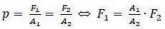
where p is pressure, F1 is the force at the small piston, A1 is the area of the small piston, F2 is the force at the large piston, and A2 is the area of the large piston.
Of course, the energy conservation continues to apply unchanged: to lift the large piston by a distance s2, it is necessary to move the small piston by an appropriately longer distance s1. The following applies with the above-mentioned equation:

where s1 is the moving distance at the small piston and s2 is the moving distance at the large piston.
This principle also applies for any number of interconnected hydraulic cylinders. If all these cylinders were to be identical and were, thus, to have the same area (A1 = A2), it immediately becomes clear from the above-mentioned formulae that the force F1 is always identical to the force F2, or the distance s1 is always identical to the distance s2.
The cited patent utilizes exactly this fact: all ropes will always align themselves with each other if their end connections terminate on hydraulic cylinders that are all interconnected and have the same area. The alignment takes place, theoretically, to zero. In reality, of course, there is always friction inside the cylinders, which only permits alignment to a certain extent. (In the case of smart construction and selection of seals, alignment to 40 N per cylinder is certainly possible.)
Practical Implementation for Elevators
To apply the principles for new systems, as well as for modernizations on elevators in a simple and inexpensive manner, the following boundary conditions should be observed during implementation of the principles:
- Minimum construction size — The rope plate should not have to be altered, and, in the same way, no construction space should be lost (particularly for elevators without machine rooms).
- Cascading — Simply retrofit elevators with any number of ropes, without commissioning.
- Safety — The rope end fastenings should not be altered.
- Longevity — Several million cylinder strokes or elevator movements should be achievable.
Under consideration of the stated conditions, the following design was developed and implemented: as can be seen in the isometric representation, the individual cylinders can be mounted onto the existing rope plate if, as in this design, their outer diameters do not collide with the rope distances. For this reason, the diameters were selected so that they are in accordance with the buffers or spiral springs usually used.
Diagonal Pull Compensation
To minimize the construction of the hydraulic cylinder — after all, this is the prerequisite for simple assembly without conversion measures on the system — a further component is required: the so-called wobble plate.
In particular, regarding 2:1-suspended elevator systems designed without machine rooms, a massive diagonal pull of up to an angle of 7° generally occurs on thin ropes at the uppermost stop.
This diagonal pull is, of course, repeated in the threaded rod of the suspension means but must never affect the hydraulic cylinder. If the hydraulic cylinder were thus to stand diagonally on the rope plate, the flow of force in the cylinders would generate transverse forces in the cylinders.
To absorb such transverse forces with low wear, the cylinders would have to be extremely overdimensioned for the application purpose. This would render their installation into the existing rope plate impossible.
Wobble plates incorporated between the cylinder and rope plate ensure that the cylinder always remains aligned parallel to the suspension-means end connectors, and that no transverse forces are generated.
Effects on Individual Suspension-Means Tensions
The effects of the hydraulic rope alignment are substantial and can, for example, be visualized using the above-mentioned rope-tension measuring device. In Figure 4, the tension progression of the individual ropes in case of deactivated rope alignment are presented in the left diagram. It is clear to see how the individual ropes “run apart” or even absorb and transfer loads in opposite directions to each other. This leads to individual ropes bearing far more load than others and thus reduces the lifetime of them (and, therefore, of the entire rope set) and may damage the traction sheave and deflection rollers.
The right diagram shows the individual rope tensions in case of active hydraulic rope alignment: The overall load distributes itself optimally between the individual ropes. The load progressions in the individual ropes run parallel; none of the ropes bears a disproportionately larger or smaller load than the others. There are still small differences between the ropes, which are caused by the fact that the physical principle cannot be ideally transferred into the real world, and, therefore, inner friction exists in the cylinders.
Summary
The decisive factor contributing to the lifetime of suspension ropes — subsequent to their correct dimensioning and after ruling out avoidable errors in installation and rope maintenance — is, above all, the optimum rope tension in every position within the shaft. The trend toward multiple suspensions is also having an effect on comparatively small elevator systems. Formerly, they were seen only on high-rise elevators featuring a travel height of several hundred meters: tiny deviations in the traction-sheave grooves and rope diameters lead to major differences in the individual rope tensions, as the small traction sheaves of elevators without machine rooms carry out a similar quantity of rotations as the traction sheaves in high-rise elevators.
Even if the individual rope tensions are adjusted periodically using high-precision measuring technology, wear on the rope cannot be prevented, as such an adjustment can only be undertaken for one position of the cabin within the shaft.
A solution that substantially minimizes rope wear must, however, be applied across the entire travel height and take effect at every position of the cabin within the shaft.
The solution presented in this article in the form of a hydraulic rope alignment will substantially reduce the rope wear on any elevator system, even if it is installed into an already-damaged system, and it has the marked advantage of requiring no additional electricity, sensors or control circuits, and can be very easily installed without conversion measures being required.
-
- Figure 1: Progression of the individual rope tensions during upwards elevator travel of a 1:1 suspended elevator
-
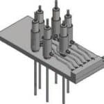
- igure 2: Schematic diagram of hydraulic rope alignment; the interconnected cylinders optimally align the ropes, even during movement.
-
- Figure 3: Wobble plates as compensation for diagonal pull facilitate small constructions that can be incorporated into the existing rope suspension.
-
- Figure 4: Rope tension progression with deactivated hydraulic rope alignment (left) in comparison to active hydraulic rope alignment (right): the improvement by approximately 25% can clearly be seen, which almost doubles the lifetime, according to Feyrer.
-
- Figure 4: Rope tension progression with deactivated hydraulic rope alignment (left) in comparison to active hydraulic rope alignment (right): the improvement by approximately 25% can clearly be seen, which almost doubles the lifetime, according to Feyrer.
References
[1] Feyrer, Prof. Dr. K. Drahtseile: Bemessung, Betrieb, Sicherheit. 2nd Ed. Springer Verlag, Berlin Heidelberg, New York (2000).
[2] Pfeifer Drako, Scheunemann, Dr. W. U091123_Seilspannung, Mühlheim a.d. Ruhr (2009).
Get more of Elevator World. Sign up for our free e-newsletter.


