Tall Stories in the Big Apple
Mar 1, 2017
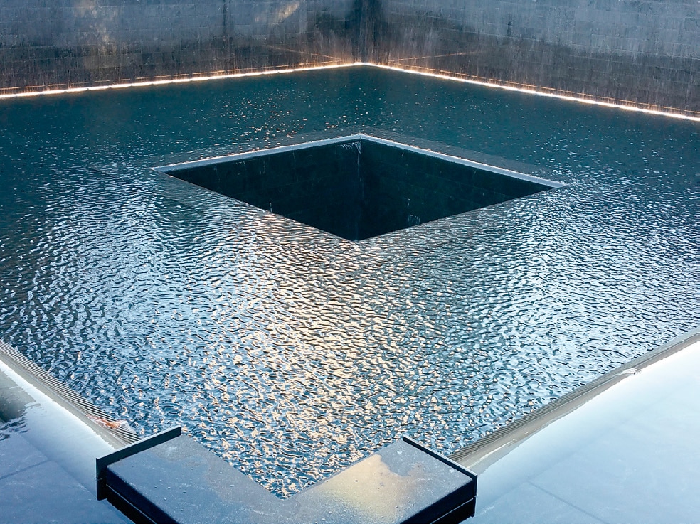
Elevator entrances reach new heights in 3 WTC, and 10 and 35 Hudson Yards.
Twenty-foot-high elevator entrances?
At first blush, this sounds like the stuff of imagination or a futuristic movie set. However, this is the current reality at Tower 3 of New York City’s (NYC) World Trade Center (WTC) complex, where a major OEM is in the process of installing 27 such oversized entrances designed and supplied by its strategic supplier, Columbia Elevator Products Co. Inc. Among the world’s most iconic sites, 3 WTC is located at 175 Greenwich Street at the southern tip of Manhattan (ELEVATOR WORLD, July and September 2016, and February 2017). Standing 80 stories and nearly 1,100 ft., this building, with its soaring lobby, is scheduled for completion next year.
The design of 3 WTC was brought to life by noted architect Richard Rogers of Rogers, Stirk Harbour & Partners. The plans called not only for these previously unseen entrance heights, but for a revolutionary approach to elevator entrances and lighting applications as a certifiable part of their structure. Such bold vision has been trending of late, with architects increasingly stretching the limits of design and code compliance to meet the demands of today’s dynamically evolving, highly competitive real-estate environment. In the elevator industry, market demand drives innovation, and, in 2017, the elevator entrance has shown unending innovation since its rudimentary beginnings over a century ago. Even in more recent times, entrance heights of 20 ft., or even half that, were unfathomable, not as much because of aesthetic issues as matters of safety.
Louis “L.J.” Blaiotta, Jr., Columbia’s CEO, said:
“Elevator entrances play much more of a critical role in safety than many people pause to consider. Most look at elevator entrances and today’s sliding doors as purely an architectural feature — to ‘pretty up’ the property – without giving much thought to their two most fundamental safety functions: first, to protect the opening and keep people from accidentally falling into the shaft when the car is not there, and, second, to prevent fire from moving floor to floor in an open shaft, which, in effect, acts like a giant chimney. Fire safety remains a critical and, sometimes, restrictive factor in the design and functionality of today’s aesthetic adventurism. The design challenge for oversized entrances is to overcome some of the legacy restrictions, while maintaining safety and support of continually advancing architectural trends.”
Before drywall was used in the construction of multistory buildings, elevator entrances were designed and built for the then-prevailing masonry construction of openings, which required that only the doors, and not the frames, have a fire-safety label. In a masonry application, it is allowable to construct a fire-rated opening with just fire-rated doors and no frame at all, as long as the code-required door-to-wall gap and overlaps around the doors are maintained. However, frames nonetheless have often been used in masonry environments because of the precision they contribute to the fit of components. When openings are cut into a preexisting masonry wall, it is very difficult — if not impossible — to achieve perfect alignment between elevator-car and hatch-side components. This alignment situation is ameliorated by the use of steel frames, which are installed prior to the wall construction and act to ensure elevator-equipment alignment. In such masonry circumstances, only the doors require UL labeling, while masonry “alignment” frames do not.
A subsequent step forward in fireproof construction came with the invention of drywall, which became highly popular due to its lower cost and weight, faster installation speed, and allowable design flexibility. In a fire-rated shaft, drywall construction is composed of a 1-in.-thick shaft-wall liner on the shaft side and two thinner sheets of 5/8-in.-thick drywall on the corridor side with an air space between. The fact that fire could work its way into that so-called “interstitial” space required capping the ends between the shaft-wall liner and the corridor liners whenever penetrations are cut into a drywall system to gain access to the shaft.
With frames already in use in masonry environments, elevator-entrance designs drifted to using the same frames as interstitial endcaps for drywall openings. This, however, led to a new set of challenges: upon installing a steel frame together with a fire-rated door and subjecting this combination to a fire test, it was found that, without masonry behind to hold the frame in place, it would suffer severe distortion. The first drywall fire tests failed, because the twisting of the frame allowed the gap between the drywall sheets to open and permitted fire to spread from floor to floor. It was determined that, to render these frames workable in a drywall application, modifications needed to be made to the design of the frame, including hooks on the back of the doors and other accommodations. Consequently, to properly regulate fire safety in drywall applications, it became necessary to obtain UL labels for the frames, as well as the doors in drywall, contrary to the doors-only requirement that is still acceptable by code for masonry.
Demand continued to develop for taller openings, more in the range of 9-10 ft., not only for aesthetic reasons, but also to create bigger service cars able to move both people and large objects within a building. If such large entrances had not been previously tested, they would not qualify for a UL label. For a time, the only UL-labeled alternative to such oversized entrances was masonry. It was inevitable that a way needed to be found to create door/entrance combinations for drywall that met UL standards.
Continued Blaiotta:
“The first successful fire tests for drywall door and frame combinations were for very small openings because of the design difficulties these presented. As 7- and 8-ft. entrances became standard, architects began striving for taller entrances to achieve the bold new looks they were imagining and needing to create to remain competitive. The bigger the openings became, the more difficult the ability to conduct fire testing. To accommodate this industry need, we sought ways to create progressively larger and larger fire-rated door and frame combinations that would pass the required fire test in all types of wall systems.
“At first, door manufacturers in the elevator industry tested designs for masonry openings and then for drywall. After testing several permutations and combinations, we developed and manufactured revolutionary oversized solutions for both environments. The developments allowing for the 20-ft.-high entrance look at 3 WTC represent a major leap forward. While UL continued to build progressively larger testing chambers, they maxed out at 10 ft., allowing for, at most, 10-ft. opening tests. But, the larger chambers also made it possible to now introduce transoms into the fire test, permitting the use of oversized transoms. These, used in certain combinations with doors, created the opportunity to achieve dramatic new looks.”
Because the WTC is part of the Port Authority of New York and New Jersey, as opposed to the NYC Department of Buildings (which can issue design variances), it must follow ASME A17.1, requiring UL certification. But without an existing lab chamber capable of testing entrances and transoms taller than 10 ft., Columbia pursued a way to earn and receive UL oversize certificates for the 20-ft. openings. Products larger than the test chambers can only receive UL certification by following several engineering calculations and analyses to create the final procedures that must be followed for UL to grant an oversize certificate for such heights (anything more than 10 ft.). With enough supporting data from previous test results, this “engineering evaluation” is deemed to be the theoretical equivalent of testing the physical product in an actual 20-ft. chamber. Columbia, after 50 years of testing numerous door, frame and transom combinations and permutations, ultimately received permission for a 10-ft.-tall single door panel (4 ft. wide to be paired with a 10-ft. transom) and, as a result, was able to build 20-ft. openings in 3 WTC with genuine oversize certificates.
The look of the 3 WTC entrances was developed with more than a slight nod to history. The profiles of the 20-ft.-tall LED entrance insets were envisioned as an homage to the iconic profiles of the original WTC Twin Towers, a touch the designers were seeking to achieve in at least one of the buildings in the new WTC complex. While these entrances bear some resemblance to those from the original towers, there are significant differences. The original 1973 entrances had unrated faux transoms, strictly for appearance, glued to a fire-rated wall. The entrances now going into the new WTC building feature true, fire-rated transoms, despite their additional height.
Blaiotta explained:
“There are two types of transoms: projected, where the doors go behind the transom, and flush, where the transom and doors are in the same plane. Projected transoms are the more common choice, since they are much easier to build. But, for 3 WTC, the architect wanted a flush transom, where the doors themselves appear to be 20 ft. tall. This ruled out the transom treatment used in the original WTC, since that would not allow for the desired look. Columbia’s solution was to cut a 20-ft. hole in the wall, refill it with fire-rated doors at the bottom and place a flush, fire-rated transom at the top.”
While Columbia had certification for 10-ft. doors, the cabs could not be that tall, since all floors above the lobby had only 8-ft. openings. To achieve the outsized flush look in the lobby, Columbia’s solution was to overlap a 10-ft. door behind a 12-ft. transom. With two extra feet of transom extending down over the door, the desired appearance of a 12-ft. transom and an 8-ft. door is achieved. As in all-flush transom arrangements, the bottom part of the door was made thicker than the top, allowing the top of the door to “overlap” the transom, with the bottom of the door extending out enough to be flush with the face of the transom.
Another revolution in the design of these new entrances, with dramatic effect, was to equip them with top-to-bottom LED light fixtures, within the depth or “throat” of the jamb, that glow as the car arrives at the lobby. The challenge was that the architect did not want to see any of the elevator jamb. In modern masonry applications, it is common to have marble or steel plates extending directly up to the edge of the doors without any of the entrance frame in sight, but in this situation — because the architect wanted a full 48-in. opening, and the maximum allowable opening width of the door frame was 48 in. — placing two 2-in. lighting units in the left and right throats of the openings would make the opening 4 in. smaller.
Blaiotta added:
“Our solution was to design an unusual jamb profile, with a pocket in the entrance jambs to allow the insertion of the lights in a way that didn’t physically attach to our entrances at all, because, if we made a mechanical connection to our frame, it would have violated the UL label. Instead, the frame was pocketed to allow installation of light fixtures in front of, but not touching, our frame. The trim of our jamb was made of the same material as the light fixture itself, creating the illusion that you’re looking at the frame of the light fixture, when, in reality, a piece of the light-fixture trim is actually the elevator entrance jamb — a very skinny profile — and the rest is the light fixture itself. They’re so close together and perfectly aligned that the brain interprets it all as one big light fixture. This allowed us to create a masonry entrance with a 48-in.-wide opening, even though the light fixtures actually required 52 in. of width.”
Another example of Columbia’s approach to architectural challenges can be found in a drywall environment just 30 blocks north of the WTC at the in-progress Hudson Yards development. Here, Columbia received an OEM order for 10 Hudson Yards, where the architect wanted the appearance of floor-to-ceiling openings in the 17-ft.-tall lobby with a center-opening look as if the doors opened all the way to the top. A transom is usually one large panel above the doors that open below, but in this case, the appearance is of a 17-ft. center-opening door from bottom to top. According to code, fixed/non-operable fire-rated door panels can be used in place of a transom panel to create the illusion of a floor-to-ceiling door system. Actually, there is one set of lower doors that opens and another set of doors above that do not open. In this situation, to satisfy requirements of the NYC Department of Buildings, Columbia engaged a professionally licensed engineer to conduct an analysis of design and construction as the basis for a variance. This resulted in the desired look, featuring 8-ft. doors and 9-ft. transoms with vertical and horizontal seams between.
Over the years, Columbia also tested and received a certificate for 48-in.-wide single-speed doors, a very unusual alternative to the two-panel center-opening doors commonly used for this width opening. At 35 Hudson Yards, for a job ordered by another major OEM that will be installed later this year, the requirement is for a one-panel single-speed door in an opening 4 ft. wide X 9 ft. high. Since Columbia had previously successfully tested a 4-ft.-wide X 10-ft.-high opening, the doors ordered for this job will not require an oversize certificate. Instead, they will simply receive a true, full UL label. In this case, the opening needed to be not only “super tall,” but also “super wide” to produce a service car using a single-speed door that, for several specific reasons, was being sought in this application.
Blaiotta concluded:
“Columbia has become a sought-after resource in the elevator industry whenever there’s a need to find solutions for innovative entrance designs. We are invited into the process early and sit with architects and bidding elevator companies, even before the job is sold. This collaborative approach allows us to explore what’s possible, to support the design of something that works in an elevator environment and can be fire rated, while still fulfilling the architect’s far-reaching aesthetic dreams. For the WTC job, we met with the architects years in advance in the conference rooms at 7 WTC. At that time, with their offices overlooking that huge hole in the earth known as ‘Ground Zero,’ we contemplated not only what could be possible, but also what would be a suitable tribute to and recognition of the past, even though the new WTC complex buildings were going to look like nothing ever before seen or built.
“I feel extremely proud of the work every teammate at Columbia is contributing toward the 3 WTC job. Plus, we all feel a bit patriotic, because the work we’re doing is contributing to the rebuild of the Ground Zero area. We want to build something moving and meaningful, so we don’t ever forget.”
Get more of Elevator World. Sign up for our free e-newsletter.


