Historic U.K. boat lift used a pair of hydraulic elevators to creatively overcome a stiff challenge.
On February 26, 1877, the well-known English botanist and evolutionary theorist Hewett C. Watson (1804-1881) sent the following letter to civil engineer Sidengham Duer (1836-1886):
“‘Hydraulic Canal Lift’ is returned herewith. Many thanks for the loan of the paper, which has been read with no little interest as one giving me new ideas on its subject. Truly, it is a vast command of physical power to lift up 240 T. to a height of 50 ft. in the short space of 3 min. or less. It has been customary for writers, who seek to exalt the Ancients over the Moderns, to ask how such great blocks of stone as were used in the pyramids could have been moved and elevated. But, modern engineers really accomplish far greater feats by more skilled use of natural forces.”
The full title of the paper referenced in the letter was “Hydraulic Canal Lift at Anderton, on the River Weaver,” written by Duer. The paper had been presented at a meeting of the British Institution of Civil Engineers on March 21, 1876, and was later published in its Minutes of Proceedings. While Duer’s reasons for sending a copy of his paper to Watson are unknown, the enthusiasm with which Watson viewed its contents is evident. As a proponent of the emerging concept of evolution, he clearly saw the lift as illustrating the natural development of modern engineering as it surpassed the work of the “Ancients.”
The “lift” praised by Watson was, in fact, a system composed of a pair of hydraulic elevators that transported barges between the Weaver River and the Trent and Mersey Canal. The project began in the early 1870s with the recognition that increased barge traffic and trade on both waterways would benefit from a connecting link. The critical design challenges were the topography and vertical distance between the two waterways: a height of 50 ft., 4 in.
Edward Leader Williams (1828-1910), a civil engineer associated with the Weaver Trust (the company that managed navigation on the river), was the first to propose using hydraulic elevators to move barges between the waterways. Williams hired Edwin Clark (1814-1894) to develop the scheme, and Clark, in turn, engaged Duer, who described his role in the project as focused on the “arrangement of the details.”[1] John Watt Sandeman (1842-1927), who replaced Williams as the Weaver Trust’s engineer just as the project was starting, also contributed to the design. While Clark is typically credited as the lift’s primary designer, it is interesting that it was Duer’s presentation and subsequent publication (which included seven detailed drawings) that brought the system to the public’s attention. The paper received a Telford Premium in 1876 from the Institution of Civil Engineers in recognition of the importance of its subject matter and the quality of Duer’s presentation.
The lift employed a relatively simple design. The hydraulic elevators were connected such that the downward action of one essentially raised the other. When the lift was stationary, one car was at the top (the canal level), and the other was at the bottom (the river level). The “cars” were wrought-iron troughs that were 75 ft. long, 15.5 ft. wide, and 9.5 ft. deep in the center and 7.5 ft. deep at the ends. They also had gates at each end, which could be raised to allow barges to enter and exit. Each trough was designed to carry water with a depth of 4.5 ft., and they were sized to carry either two small barges (average capacity of 30-40 T. each) or one large barge (average capacity of 80-100 T.). The combined weight of the water and barges was approximately 240 T. When a trough was at the river level, it was submerged such that at least 5 ft. of water could enter, which allowed the easy passage of barges in and out. When the trough ascended, 12 siphons along its length drained the excess water until it reached the design depth of 4.5 ft. An accumulator powered by a steam engine provided additional hydraulic pressure as needed to raise loads.
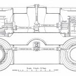
Each trough was carried by a single, centrally located, 3-ft.- diameter cast-iron ram or piston. The rams were attached to the troughs by a 3.5-ft.-deep wrought-iron socket. Wrought-iron “cantilevers” radiated from the socket to the sides of the trough to help channel the weight to the center. The corners of the troughs were also fitted with cast-iron guide blocks that ran in channels in the columns framing the lift shafts. Each ram was composed of three sections “joined together by flanges and bolts. The flanges of the rams were covered with red lead before being bolted together. The flanges of the presses, besides red lead, had a ring of lead wire [placed] between them, which, being squeezed flat by the pressure of the bolts, made a watertight joint.”[1] While the operation of the rams followed a normative pattern for direct hydraulic systems, it is important to note that the stuffing boxes were at the bottom of the water-filled “pit.” To facilitate maintenance, a 4-ft., 4-in. diameter wrought-iron tunnel was placed under the pit. The tunnel also provided access to a valve box that controlled the system’s operation.
The lift’s simple design meant that it could be operated by a team of five workers: three assigned to operate the gates that allowed barges to enter and exit, one assigned to manage the steam engine and accumulator and one who controlled the elevators’ operation from the “valve house” atop the lift. The initial design specifications called for the lift to transport barges between the waterways in no less than 3 min. When the lift opened in 1875, the average lift time was 2.5 min. The hydraulic elevators at the Anderton lift successfully carried barges to and from the canal and river from 1875 to 1908, during which time they moved approximately 5 million T. In 1908, the hydraulic system was replaced by a counterbalanced rope system designed by John Arthur Saner (1864-1952). Like his predecessor, Saner memorialized his work in a paper presented to the Institution of Civil Engineers and published in its minutes.[2] In his paper, Saner also recounted a brief history of the hydraulic elevators that permits a unique look at their operation.
During their 30-year history, the elevators required normal maintenance and survived several accidents and system failures:
- February 21, 1881: A piece of a “hard substance” of unknown origin was somehow carried into the pit, and when the trough descended, instead of being crushed between the trough’s bottom and the top of the wrought-iron service tunnel, it punched a hole through a tunnel’s roof.
- July 1881: The gland of the accumulator stuffing box was replaced.
- April 26, 1882: The top of one of the main cylinders burst, which let down the ram and trough, which was at the upper level. The cause was found to be the 4-in. hole required to receive the pipe that allowed the flow of water between the main cylinders. The solution was to replace the large single pipe with four smaller pipes, which evenly distributed the pressure around both cylinders.
- March 23, 1887: One of the cylinder glands “gave way.” It was “repaired with a wrought-iron plate that lasted until June 1891, when it was renewed with a stronger cast-iron section inserted in three parts, as it was not possible to get a complete ring in position at once.”
- April 1894: A second cylinder gland was “renewed” following the method employed in 1891.
- April 1898: One of the main pressure pipes failed.
- August 1898: The main equilibrium pressure valve, which regulated the flow of water between the main cylinders, failed.
- June 1899: Several pressure pipes failed.[2]
Saner also described an additional and persistent problem that had plagued the system: the gradual deterioration of the rams. By 1882, the lift’s operators noticed that grooves had begun to appear on the rams’ surfaces. Workers carefully dovetailed lengths of soft copper into the grooves to maintain a watertight passage through the stuffing boxes. The deterioration continued until 1895, by which time it was estimated that more than 750 lb. of copper had been used, with some strips wider than 3 in.
Saner had joined the Weaver Trust in 1885 as an assistant engineer, and, three years later, he became the organization’s lead engineer. By the mid 1890s, he had begun to suspect that the cause of the rams’ continued grooving was not due to their material or the design of the stuffing boxes. Instead, he suspected a problem well known to 21st-century engineers — water pollution. The water used to power the rams was taken from the Trent and Mersey Canal, the banks of which were lined with “numerous salt and chemical works.”[2] Saner suspected that “electrolytic action, caused by the quality of the water, was responsible for the damage, rather than the mechanical friction of the packing.”[2] A series of experiments carried out in January 1895 confirmed his suspicions, and Saner devised a system that condensed the exhaust from the steam engine, thus creating a relatively contaminate-free water source for the elevators. Saner reported that, “although the water so obtained was not entirely free from grease, there was nothing to do any harm, and the arrangement,” in his opinion, “prolonged the life of the rams for nearly 10 years.” Saner’s 1908 design for the replacement of the original hydraulic system, described by him as a “reconstruction” of the Anderton lift, will be the subject of a future paper.
Background
This month’s article was inspired by David Cooper’s paper “Boat lifts in the UK,” which was presented in 2015 at the Fifth Annual Symposium on Lift and Escalator Technologies. Cooper’s paper planted a seed that led to a search for original copies of materials associated with the Anderton lift. This search yielded a copy of Duer’s original paper, which included Watson’s letter to Duer “tipped” into the front. This happy accident permitted the illustration of the connection between the 19th-century worlds of modern scientific thought and modern engineering.
This investigation also served as a reminder of the darker side of industrialization, in the pollution of the Trent and Mersey Canal. The benefits found in having strong connections between the worlds of science and engineering, as well as the potential environmental dangers of manufacturing, remain critical aspects of life in the 21st century.
-
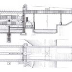
- Figure 1: Plan and section of the Anderton Canal Lift (1875)
-

- Figure 2: Section of the Anderton Canal Lift (1875)
-
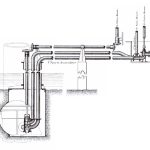
- Figure 3: Detail of original piping to ram cylinder (1875)
-
- Figure 4: New piping design for the flow of water between the main cylinders (1882)
-
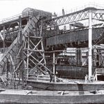
- Figure 5: Anderton Canal Lift (circa 1900)
-

- Figure 6: Anderton Canal Lift (circa 1900)
References
[1] Sidengham Duer. “Hydraulic Canal Lift at Anderton, on the River Weaver,” Minutes of Proceedings of the Institution of Civil Engineers; With Other Selected and Abstracted Papers, Session 1875-76 – Part III (1876).
[2] John Arthur Saner. “Reconstruction of the Canal-Boat Lift on the River Weaver at Anderton,” Minutes of the Proceedings of the Institution of Civil Engineers (1910).
Get more of Elevator World. Sign up for our free e-newsletter.