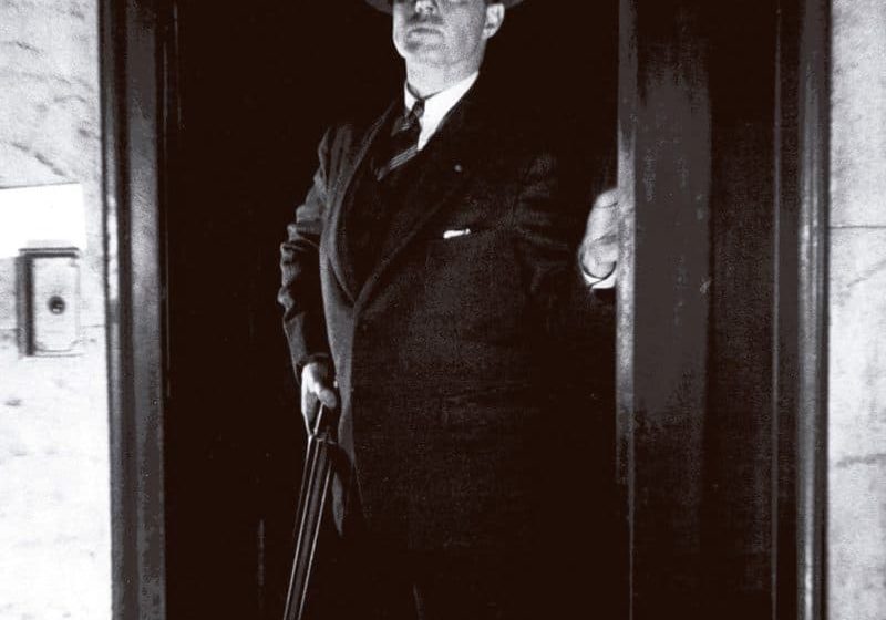
The Early History of Cable-less Elevator Systems
Sep 1, 2015
Early designs for cable-less, self-propelled, multicar elevator systems that inspired such designs as the MULTI
Not long after the official announcement of ThyssenKrupp’s MULTI system (“A Paternoster for the Future,” ELEVATOR WORLD, February 2015), your author found an article with the following title: “New Elevator Works without Cables.” Given the extensive press coverage that accompanied MULTI’s launch, finding an article with this title seems unremarkable. However, this assessment changes when the publication date is revealed: the article appeared in the September 1934 issue of Popular Science. The brief article described and illustrated an elevator system that employed multiple cars designed to operate under their “own, self-contained power in a system upon which a New York inventor has received a patent.”[1] This article prompted two questions: who was the unidentified inventor and, more importantly, were there other early designs for cable-less, self-propelled, multicar elevator systems? The search for answers led to the identification of the unnamed inventor (and finding his patent), as well as the discovery of three additional patents that concerned similar designs.
The first cable-less elevator designs date from the 1880s. These schemes employed an electric motor mounted on the car, which drove worm or pinion gears that engaged racks or screw shafts. Designs for rack-and-pinion and screw-shaft elevator systems were patented well into the early 20th century. However, these systems followed the paradigm of traditional elevators in that they were intended to operate in a single vertical shaft. The early 1930s witnessed a brief flurry of patents for cable-less elevators that were intended to move continuously throughout a building. The impetus for these schemes appears to have been the rapid growth of the skyscraper in the 1920s and 1930s. The rationale for the proposed new elevator systems included the desire to reduce the amount of space devoted to elevator shafts.
The first patent examined was by Maurice E. Breed of St. Louis: “Safety Cableless Multiple Elevators,” U.S. Patent No. 1,902,946 (March 28, 1933). This was Breed’s only patent, and it appears he was a local physician interested in technical innovations. (The 1912 edition of The Book of St. Louisans listed his hobbies as “automobiling and photography”). While his amateur inventor status may explain the eccentric aspects of his design, there is little doubt regarding its ingenuity. Breed sought to:
“. . . provide an elevator construction designed and adapted for use in buildings of the greatest height comprising an endless shaft through which a plurality of elevators operate in spaced relationship, so that a single endless shaft serves as a passage for any desired number of elevators as required by the height of the building and [provide an] improved mechanism for propelling the elevators along and through said shaft without the use of cables and similar hoisting devices.”[2]
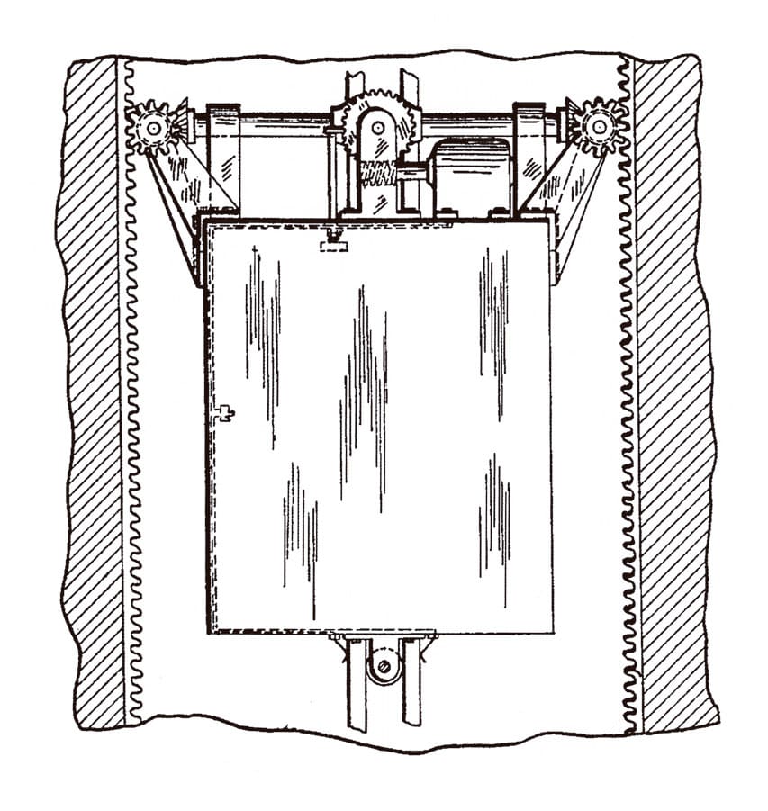
The design was a variation of a rack-and-pinion scheme with the electric motor and gearing located on top of the car and designed to travel around curving racks at the top and bottom of the shaft (Figure 1).
One of the intriguing aspects of Breed’s design was that the car traveled “upright” while ascending and “inverted” when descending (Figure 2). This meant that all ascending passengers were required to exit before the car began the transition to its descent and that descending passengers (who stood on the car’s “ceiling”) exited prior to the car beginning its transition to its ascent. This movement pattern required the presence of an operator to both run the car and ensure that passengers departed prior to changes in direction. However, Breed also imagined that the operator would remain in the car throughout its entire journey:
“The operator. . . remains in the car during the rise and descent. During the rise of the car, the operator stands upon the floor of the car; when the car reaches the top and passes through the curved connection from the ascending portion to the descending portion of the elevator shaft, the operator steps onto and stands upon the inside of the lower side wall of the car; and when the car passes into the descending portion of the elevator shaft in inverted position, the operator steps onto the inside of the top of the car and stands thereon until the car reaches the curved connection from the descending portion to the ascending portion of the elevator shaft. The operator then steps onto the inside of the lower side wall of the car and stands thereon until the car enters the ascending portion of the elevator shaft, whereupon the operator steps onto the floor of the car for another round trip.”[2]
This description prompts an image of an athletic (or perhaps acrobatic) operator in an elevator car with (by the end of a busy day) footprints covering almost every interior surface.
The second patent for a cable-less system was awarded to Jarvis Hunt: “Elevator System,” U.S. Patent No. 1,930,239 (October 10, 1933). Hunt (1863-1941) was a well-known Chicago architect, and this was his second elevator patent. The first was awarded to Clair Foster with Hunt as the assignee: “Multiple Elevator System,” U.S. patent No. 849,840 (April 9, 1907). This design featured several cars operating in the same shaft; it was not cable-less and did not have continuous motion. Hunt’s solo effort was a design that featured multiple cars ascending and descending through vertical shafts that featured “transverse tracks or cross-overs” that allowed the cars to move from one shaft to another. In a similar fashion to Breed’s design, each car had an electric motor mounted on top that drove a system of gears that meshed with vertical and horizontal racks and guide rails (Figures 3 and 4). However, unlike Breed’s, Hunt’s design allowed the cars to remain upright throughout their entire journey.
Given that his design allowed multiple cars to move at the same time, Hunt recognized that he needed an effective signal system. He proposed that “a system of block signals would have to be put into effect and the operation of the cars carried on according to schedule in order to avoid confusion and delay.”[3] The decision to use block signals is of interest, because, while it was a signaling system designed to control complex traffic patterns, it was designed to control the movement of trains, not elevators. In the early 20th century, this system was defined as follows:
“A block is a length of railroad track of defined limits, the use of which by trains is under the control of one or more block signals. A block signal is a fixed arrangement controlling the use of a block. . . . A block system is a series of consecutive blocks controlled by block signals. A home signal shows the condition of the block directly in front of a moving train, and a distant signal the condition of the second block in front or the block in the rear of the home block. An advance signal shows the condition of a block in conjunction with the home signal of that block. It is placed in advance of the home signal.”[4]
Hunt’s division of his system of shafts into a series of blocks or zones provides an intriguing conceptual image with regard to elevator traffic control and service.
The third patent examined for this article revealed the identity of the unidentified New York inventor featured in Popular Science and his patent: Eugene Phillips of New York, “Elevator,” U.S. Patent No. 1,953,772 (April 3, 1934). Regrettably, nothing is known about Phillips at this time. His only other patent concerned an improved ashtray designed for use in automobiles and train cars. Nonetheless, Phillips had a clear understanding of the design problem associated with elevator use in tall buildings:
“In high buildings, the long length of cable necessarily required has presented many aggravating problems, which increase with the increasing height of the buildings, and demand for better service. It is one of the objects of the present invention to eliminate the use of cables entirely and to operate the cars directly by motive power, and further, has for its object means for increasing or decreasing the number of cars in operation during the various hours of the day without shutting down any particular shaft.”[5]
His solution was another variation of a rack-and-pinion scheme: he employed a “motor mechanism” that consisted of an electric motor and a massive worm gear mounted in a pivoting ring or frame on top of the car. The system featured two guide rails that framed a center rack. The latter accommodated the worm gear, while the guide rails provided tracks for wheels located on the sides of the pivoting frame (Figure 5). As the car moved, the worm gear rotated to match the curvature of the shaft, and the car was held upright “hanging from the motor mechanism. . . much the same as a pendulum.”[5] Although Phillip’s patent drawings clearly illustrated the critical components of his design, the perspective drawing that accompanied the Popular Science article captured the excitement associated with the prospect of a cable-less elevator (Figure 6).
The fourth patent for a cable-less system was granted to John T. Austin: “Elevator,” U.S. Patent No. 2,052,690 (September 1, 1936). Austin (1869-1948) was the most prolific of the inventors discussed thus far, with more than 25 patents to his credit. However, like the others, his primary professional expertise was not vertical transportation — he was a cofounder of Austin Organ Co. of Hartford, Connecticut, and was a well-known pipe-organ designer. Austin’s foray into the world of elevator design, which occurred during the height of the Great Depression, may have been an attempt to imagine a new direction for his struggling company. His design employed an innovative approach that moved away from the rack-and-pinion paradigm. He proposed using wheels or “resilient tires” mounted on the top and bottom of the car that ran along smooth guide rails. The top and bottom of the car were equipped with four sets of two tires driven by an electric motor (Figure 7). The wheels were held against the guide rails by a system of springs and drive shafts:
“[The] action of the springs in establishing and maintaining frictional engagement between the rubber tires and the tracks is supplemented by arranging the drive connection between the drive shaft of the motor and the driven shafts of the wheels so that the drive thrust is in a direction to force the shafts apart and to urge the wheels and tires toward their respective tracks. With such an arrangement, the cars are practically wedged between the opposite sidewalls of the shafts.”[6]
To facilitate the movement of cars between shafts and the addition or subtraction of cars from service, Austin designed a “transfer mechanism” that attached to the side of a car and pushed or pulled it in or out of the main shaft and parked it in a secondary shaft (Figure 8).
Austin’s patent also includes an image that indicates he realized his design could move horizontally, as well as vertically. This illustration depicts a series of vertical and horizontal shafts that somewhat resemble images associated with the design of MULTI (Figure 9). However, Austin’s description of this image is surprising in that he says it represents “a diagrammatic view of a hill or mountain provided with shafts of various levels in which a car is adapted to travel.”[6] While his inability to imagine his multidirectional, multi-shaft concept applied to a building is puzzling, it is important to note that all of the other designers proposed that passengers would only access cars in vertical shafts. The fact that Austin articulated the possibility of horizontal in the context of a cable-less, self-propelled system distinguishes his design from the others.
Of course, all four of these schemes are similar in having unresolved technical, mechanical and design issues that would have made them extremely difficult to build and would have likely resulted in their failure. However, the imagination of these designers is noteworthy as is the fact that none of them were associated with the elevator industry. While this lack of industry awareness doubtless contributed to the numerous idiosyncrasies and weaknesses found in their designs, their naivety allowed them to imagine solutions that industry insiders might have dismissed as impractical. And now, once again, with the design originating from within the world of vertical transportation, we are talking about the possibility of elevators without cables.
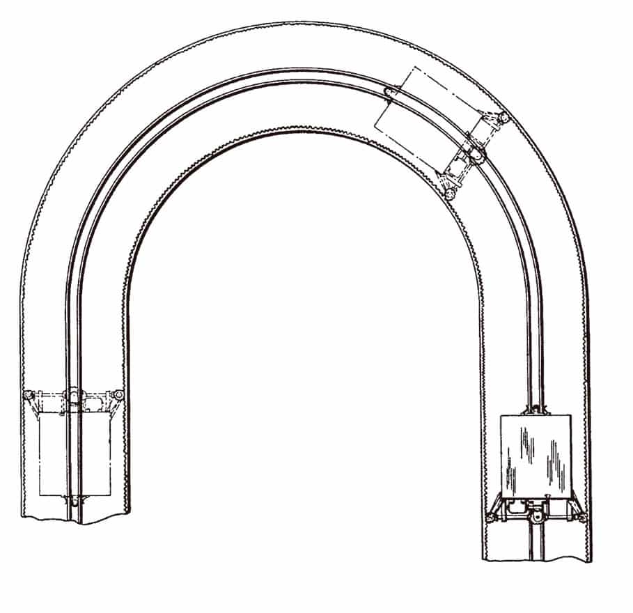
Figure 2: “Elevator shafts showing upright and inverted cars”[2] 
Figure 3: “Elevator Car” [3] 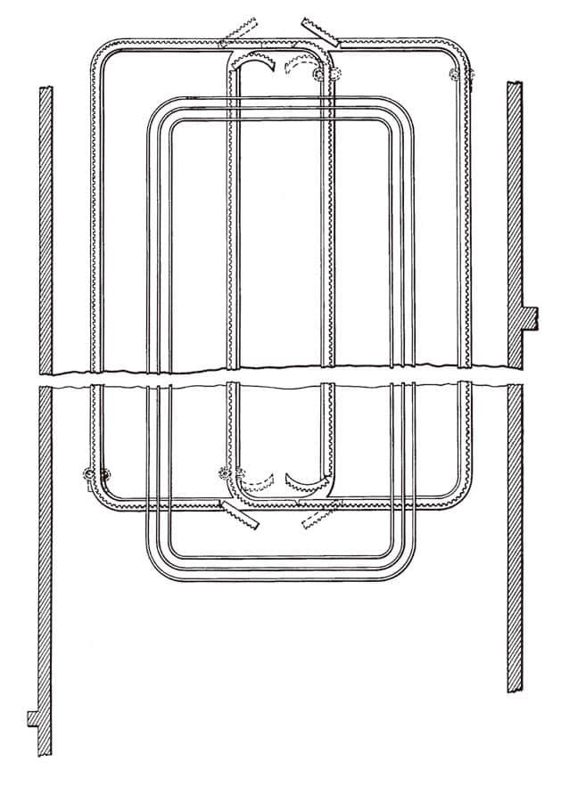
Figure 4: Elevator shafts depicted side racks flanking center power-supply strips.[3] 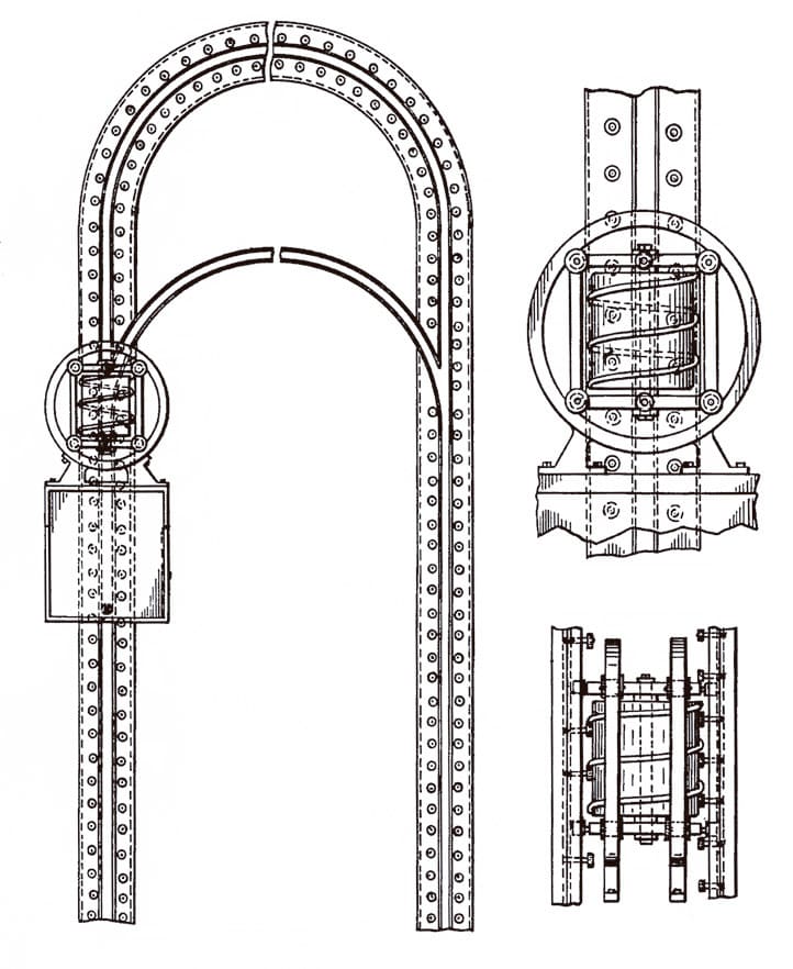
Figure 5: “Elevator”[5] 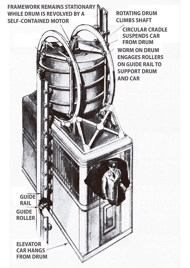
Figure 6: Perspective drawing of Phillips’ elevator car[1] 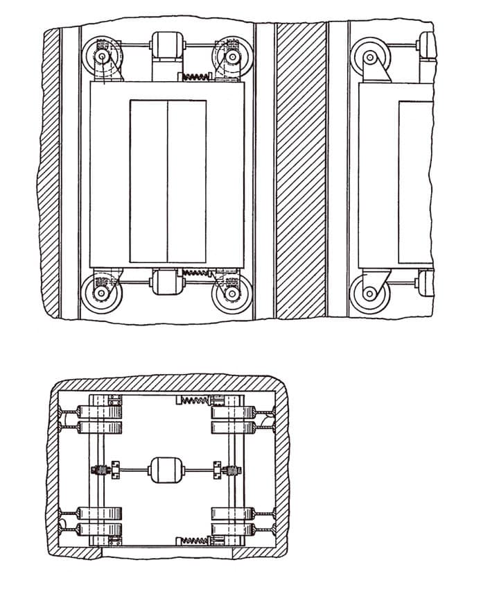
Figure 7: “Elevator car”[6] 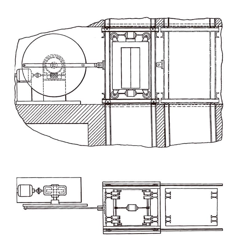
Figure 8: “Car transfer mechanism”[6] 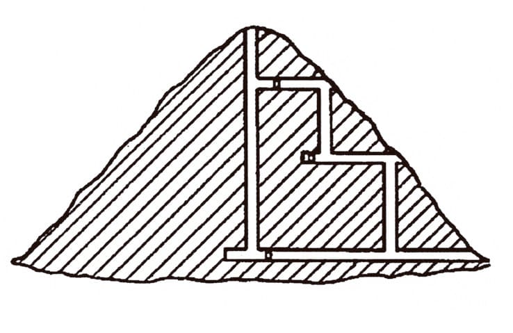
Figure 9: “Schematic drawing of a hill or mountain with elevator shafts”[6]
References
[1] “New Elevator Works Without Cables,” Popular Science (September 1934).
[2] Maurice E. Breed, “Safety Cableless Multiple Elevators,” U.S. Patent No. 1,902,946 (March 28, 1933).
[3] Jarvis Hunt, “Elevator System,” U.S. Patent No. 1,930,239 (October 10, 1933).
[4] Ralph Scott, “Automatic Block Signals and Signal Circuits,” McGraw Hill (1908).
[5] Eugene Phillips, “Elevator,” U.S. Patent No. 1,953,772 (April 3, 1934).
[6] John T. Austin, “Elevator,” U.S. Patent No. 2,052,690 (September 1, 1936).
Get more of Elevator World. Sign up for our free e-newsletter.


