The Effects of Ground Movement on Escalators
Dec 1, 2012

The role of escalators in major transportation networks such as the London Underground is discussed.
London Underground (LU) transports approximately 3.5 million passengers per day. Certain stations within the network require smooth operation for optimal function of the network as a whole. A station’s location, passenger flow and local connections (both within the subway network and more widely with external transport networks) determine what impact its operation is likely to have on the efficiency of the network as a whole.
Closure or distribution in one station could lead to significant overload on nearby stations and external transport links. Thus, continuous operation and availability of all key stations is a crucial objective in maintaining an operational network. Escalators play a vital role in transporting passengers between train tunnels and platforms, platforms and ticket halls, and to and from exits and entrances.
LU is currently under redevelopment at Tottenham Court Road (TCR) Station. The work involves the construction of a new ticket hall, three lift shafts, access to Crossrail and various retail and allied facilities. Due to customer demand and location, it is necessary to keep the station operating during the course of the redevelopment work, with minimum disruption to passenger flow. Therefore, all the station’s escalators will have to remain in operation.
As a consequence of the station upgrade and the Crossrail development, there will be significant excavation around the existing station’s structural box, in some areas to a depth of 24 m. Excavation from around the station structural box can cause the escalators’ trusses within the tunnels to physically move. Movement in the truss work of an escalator could have an impact on its operational safety and availability for use. Without functioning escalators, the station could be forced to shut down.
Geotechnical studies have confirmed the excavation work will cause a physical movement in the structure of some tunnels and escalators. The impact will vary depending on the location of each escalator in relation to the excavation. This movement can have a significant effect on the operational safety and availability of the escalators, as previously explained.
Passenger Safety First
As part of the project, LU and Tube Lines Lifts and Escalators Services, a wholly owned subsidiary of Transport for London responsible for maintaining and upgrading parts of the LU, embarked on designing a method of adjusting the escalators in three dimensions (jacking system) and installing a monitoring system on the escalators. This system will complement the LU system, which has been installed to monitor the movement in the tunnels, tracks and platforms. The objective of the escalator monitoring system is to assist in maintaining the availability of the escalators, ensure the integrity of the station structure and guarantee safety of the passengers using the escalators during the construction process.
The Tube Lines monitoring system is able to record live real-time readings and, be installed prior to commencement of the excavation activities, determine normal operational baselines. This is advantageous, because identifying real-time deviations from such baselines, allows the system to serve as an early warning mechanism if movements occur. The trends can be used to determine and predict potential structural and mechanical problems before they pose a threat to safety and operation.
The system consists of various sensor types, such as string potentiometer, strain gauges, proximity sensors, load cells and displacement sensors, all of which are installed on various locations in the machines (e.g. truss and combplate). The location of each sensor has been determined by using extensive simulations of Finite Element Analysis (FEA). Movement scenarios derived from geotechnical studies were input in the FEA simulation, and from this analysis, worse-case scenarios were forecasted against the time scale of the project. Critical alarm levels were calculated from the forecasts providing the safe limits of movement allowed for an operational escalator. The sensors are connected to an electronic system, which communicates with a storage hardware system via the Internet. Bespoke software has been written to view, plot and trigger alarms in real time.
The adjustment jacks were installed at the support nodes of escalators 3 and 5, as these escalators are the most critical for maintaining station operability. The jacking system allows for the two escalators to be adjusted to counter the ground movement, thus remaining in safe operation. The monitoring regime and any escalator jacking is overseen by an engineering panel of experts who decide, based on the monitoring information, any counter actions, jacking, following set procedures and method statements.
Tube Lines has set the mark for one of the first escalator monitoring systems, tuned and connected to surrounding ground movements. There are various advantages of such a system in terms of passenger safety and in preserving the structure integrity of the escalators. The principles and methodology of the system can be utilized for any similar development in the network. The data obtained from the project can be fed to allied industries interested in simulation. The data and trends may be of use to engineers and scientists from various disciplines.
Strategy and Methodology
Due to the upgrade and redevelopment work at TCR (Figure 1), protecting the existing underground station and its escalators has been a priority for Tube Lines. The following will examine the core concept of escalator monitoring and explain the logic of the distribution of escalator sensors. The methodology, which has been used to protect the escalators at TCR, follows these steps:
- Conducting geo-analysis
- Sensing movements in the tunnels
- Simulation and mathematical modeling
- Sensing movements in the supports, critical clearances and gaps and live data
Conducting Geo-Analysis
Tube Lines commissioned Geotechnical Consulting Group (GCG) to conduct a study to analyze the impact of the excavation work on the structures in and around the station. GCG studied the nature and type of soil layers and verified their densities. Tube Lines calculated and predicted sets of movement scenarios against the amounts of soils removed from site. Finite-element code software was used for the analysis of soil-structure interaction problems over a number of years. The analyses undertaken for this assessment comprised a series of 2D plane strain analyses and a 3D analysis. The 2D analyses modeled the existing infrastructure, excavation for the new structures, and new tunnels.
Sensing Movements in the Tunnels
Laser sensors with targets have been distributed along and across the escalator and train tunnels. Electrotilt meters have been distributed along the escalator tunnels. The laser sensors and tilt meters measure declines, rises and twists in the tunnel.
Simulation and Mathematical Modeling
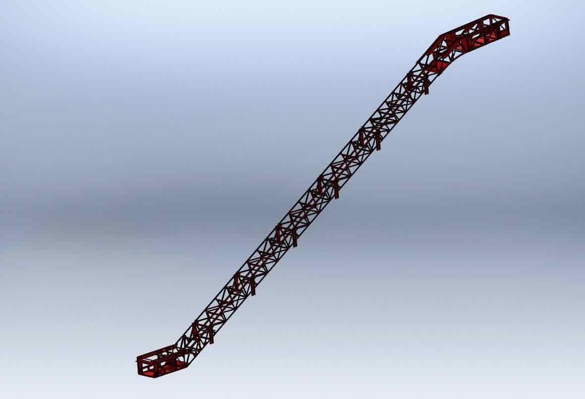
The trusses of three escalators were 3D modeled using the Solidwork simulation package (Figure 2). The total predicted movement by the geotechnical study at each support in the truss of the escalators was divided into 10 increments. The 10 incremental steps were put into the 3D model of each escalator as 10 movement scenarios. The results for each scenario were produced in the form of deflection – stress and strain distributions along the length and width of the escalator (Figures 3 and 4).
Relationships between the results of the simulation and data fed into the model (like displacements) were correlated and expressed in mathematical formulas, which were used to plot graphs between the parameters. The behavior of each parameter was plotted against a time scale to check the long-term impact of the movements (Figure 5). The graphs were extrapolated to a long-term scale to predict the escalators’ worst movement scenarios. The results from the simulation study concluded that the movements in the ground will cause the creation of critical locations (bays) in the truss. The bays have to be monitored during movement.
Sensor Distributions
Sensing Movements in the Supports
Movements in the foundations along the length and width of the escalator vary from one location to another. They subject the trusses to physical deflections, which generates stresses in the individual elements in the truss (Figures 6-8). The levels of these stresses can reach a level equal to or higher than the fatigue threshold of the material of the truss. Movements in the supports of the escalator depend on the depth and size of the excavation, which is conducted adjacent to the escalator tunnel. These movements can either cause a hump or sink in the truss (Figures 9 and 10). These changes can be gradual or sudden along the length of the escalator. Lateral gradual movement across the width of the escalator causes the truss and inner assemblies to tilt sideways.
The geotechnical study report on ground movement suggests most of the movement will occur near the tunnel, which contains escalators 3-5 (Figure 1). As a result, these escalators were equipped with sensors to monitor their structures and performance. To make sure the station remained open to passengers, at least two of the three escalators remained in operation, with one escalator in each direction. (In an extreme case, the station can remain open when there is only one escalator running, as long as it is in the up direction.)
To guarantee the structural integrity of at least two escalators (3 and 5), hydraulic jacks were installed after modifying the vertical supports in the truss (Figure 11). The jacks are capable of a vertical movement of 25 mm. The idea was to use this movement to adjust against any ground movement. A load cell was installed in each jack to monitor the vertical force at each support leg. As the vertical supports in the lower landing and along the incline were modified by disconnecting them from their plinths and installing jacks between each, the residual stresses were ignored. This means all the stresses in the truss started from zero. Strain gauges (Figure 12) were mounted in or near the critical bays to monitor the stress levels (during the rebuild stage and when the escalators were in full operation).
Sensing Critical Clearances and Gaps in the Escalators
The most safety-critical gaps and clearances in any escalator are the ones between the comb sections and step band. These clearances have to be maintained at 4-6 mm. Tread plates are bolted on top of each step in the step band. These plates have cleats that allow the step to pass through the comb sections in the upper and lower landings. A ground movement in the foundation could compromise the clearance between the comb sections and the steps, causing significant danger to passengers. A collision between the step band and comb sections can have serious implications on the structural integrity of the escalator, as it could affect many critical components and assemblies inside the escalator.
String-pot sensors have been used (Figure 13) to monitor vertical and horizontal movements in the comb sections. The body of the sensor was placed on the ground or side tabbing of the tunnel, while the string end was connected to the comb sections. A “smart step” was incorporated in the step band. The step measures strains, deflections and stresses that the step band could endure during operation. It can indirectly monitor whether the clearances have been compromised.
Sensing Live Data
A bespoke software and hardware has been designed by Arcadis and commissioned to Tube Lines (Figure 14). The system is capable of logging, storing and monitoring data, and provides real-time output data detailing levels of movement at different locations in the escalator. The system also ensures timely, controllable and accurate adjustment (if needed) during periods of ground movement. The collected data helped in form the jacking philosophy and method to adjust the escalator structure. The sensors’ outputs calibrated values, with varying current, measured using a Siemens Fastflex Remote Terminal Unit (RTU). It is possible for the RTU to interface with a computer via a network switch and communications equipment to allow monitoring from a remote location, such as an office.
Conclusions
Escalator monitoring systems were installed to mitigate commercial, safety and technical risks. They can have commercial implications by rationalizing maintenance schedules to effectively and efficiently run machines such as escalators. The systems can also monitor the impact of ground movement if there is excavation or building work adjacent to the escalators. The monitoring systems can play a significant part in ensuring the escalators are safe. They can also be used for R&D to explore behaviors and geometry of escalator trusses and their sub-mechanical assemblies.
The monitoring system, which has been deployed at TCR, is comprehensive, ensuring the operation of escalators during both normal conditions and ground movements is safe. The system consists of sensors connected to the supports of the truss in the form of load cells. The load cells are built into hydraulic jacks, used to adjust the truss and compensate against ground movements. A load cell is incorporated in each jack. The load cells measure the values of reaction forces in the foundations of the escalator when the ground movement occurs.
Critical clearances like the gap between the comb section and step band are monitored using string potentiometer and a smart step. The string potentiometer measure the clearances in millimeters, while the smart step measures the stresses and strains in the step band. The data is collected and viewed using bespoke software. A Windows interface viewer is used to monitor live data from the sensors and allows the user to download historical data. A future paper on this subject will shed light on the type, style and consistency of data logged within the system. It will also provide insight into the pattern of curves and relationships between the various sensor outputs against the ground movement. Your author’s next article will show data from the sensors against real time. Therefore, it will show the relationships between the measured parameters.

Figure 2: The complete model for one of the escalators at TCR 
Figure 3: The stress distribution in the escalator for a movement scenario 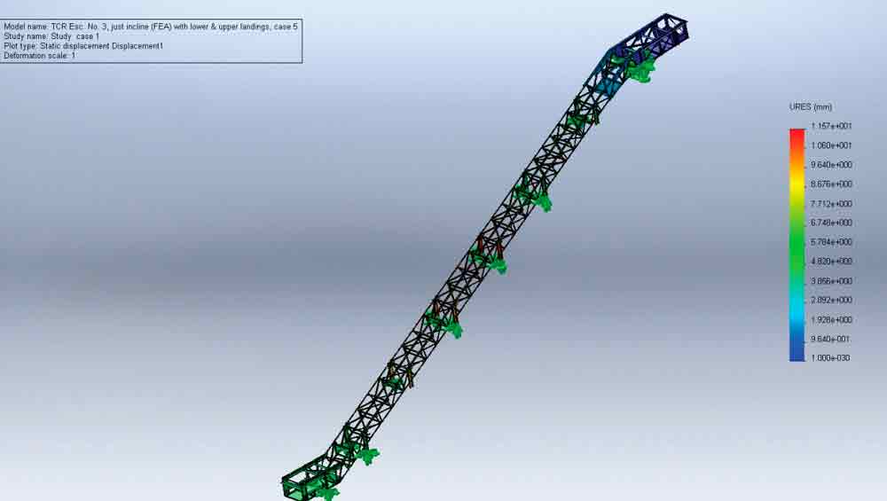
Figure 4: The displacement distribution in the escalator for a movement scenario 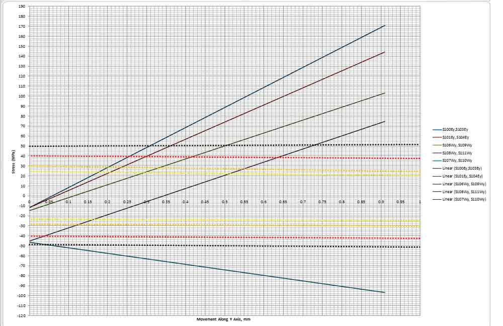
Figure 5: The predicted movement as calculated by the mathematical model 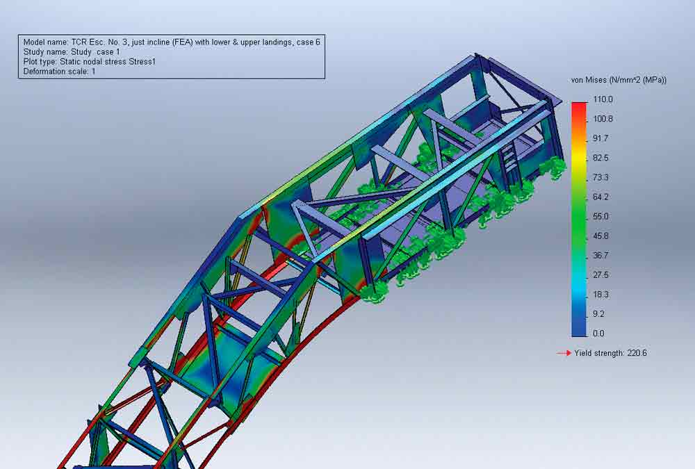
Figure 6: The stress distribution in the upper landing 
Figure 7: The stress distribution in the lower landing 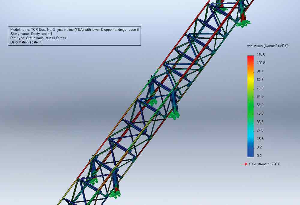
Figure 8: The stress distribution in the incline 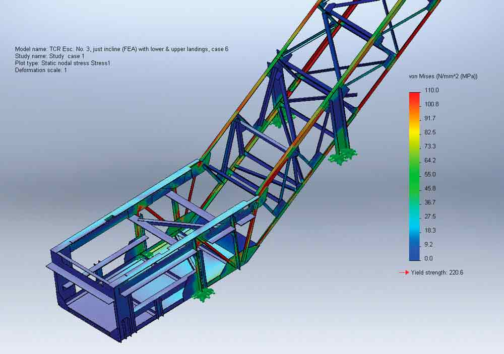
Figure 9: A hump in the incline produced from the ground movement 
Figure 10: A dip in the incline produced from the ground movement 
Figure 11: A truss support leg modified to accommodate a hydrau-lic jack and load cell 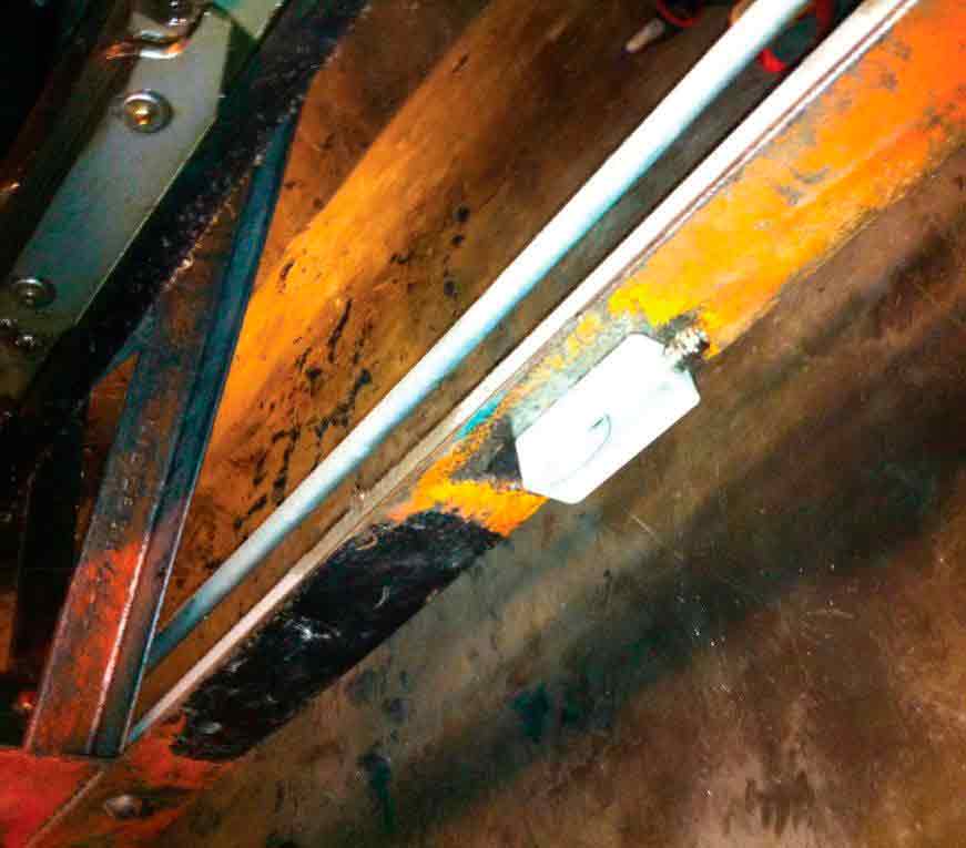
Figure 12: A container is used to protect a strain gauge (inside). The connector is used for a cable to the strain gauge. 
Figure 13: A string potentiometer to monitor movement in the combplate 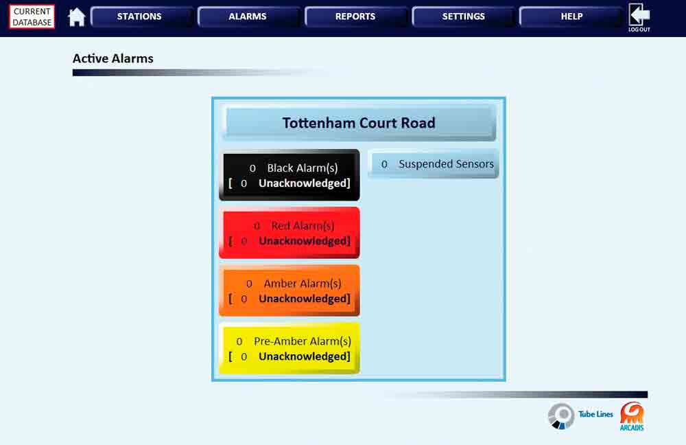
Figure 14: The software’s front window
Get more of Elevator World. Sign up for our free e-newsletter.


")


