The Electromagnetic Elevator
Nov 1, 2018
Two inventors competed to produce a precursor of today’s linear elevator concept at the end of the 19th century.
In the closing decade of the 19th century, two American engineers independently explored using electromagnets as a means of powering elevators. These efforts, when considered in the context of the development of the linear- induction motor, reveal that, as is the case with elevators designed to move vertically and horizontally, contemporary innovations often have intriguing historical precedents. The separate but almost simultaneous work undertaken by these engineers also parallels modern events in that one inventor sought to apply a system developed for an electromagnetic train to elevators, while the other sought to develop a system specifically designed for vertical-transportation systems.
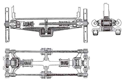
In December 1893, Paul W. Leffler (1853-1914) of Chicago founded Leffler Electro- Magnetic Railway Co. In November of the previous year, Leffler had filed an application for the first of 10 patents that concerned his design for a train powered by electromagnets. Between August 1895 and March 1896, he filed six patent applications, five of which were issued on the same date: December 22, 1896. The latter group included the only non-railway-related patent he pursued during this period: “Electric Elevator” (U.S. Patent No. 573,820). In his introduction, Leffler referenced his railway patents, noting:
“In these patents. . . I employ a magnetic field extending along the line of travel, which is produced by a series of magnets spaced apart from each other, with the adjacent members of opposite polarity, and a nonrotating armature carried by the car in position to be subject to the influence of said field, the electromagnets of which armature are preferably arranged in sets connected in series and so positioned with respect to each other and the field-magnets that the magnetic forces of attraction and repulsion cooperate to propel the car in a common direction. To control and maintain the proper magnetic relations between the field and the armature magnets, I also employ. . . an automatic pole-changing mechanism applied, preferably, in the circuit connections for the armature-magnets. In my present invention, I organize the above combination, together with certain additional features, into an elevator.”[1]
Leffler’s “organization” of his railway design “into an elevator” was expressed through his patent’s 10 pages of drawings (containing 27 figures) and six-and-a-half pages of text. His detailed presentation permits a thorough examination of his electromagnetic elevator.
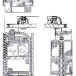
An analysis of his design reveals that he attempted to produce as normative an elevator as possible. Leffler stated the “elevator-car may be in appearance of the ordinary cage-like form.”[1] He recognized that the most important aspects of the car design were the platform, stiles, crosshead and safety plank, referring to these components as the floor, top yoke, vertical rods and bottom yoke, respectively. He stated the car would be “suspended and counterpoised in the usual way” (Figure 1).[1] His patent text implies that the counterweight equaled the weight of the car, which was somewhat unusual, as, by the 1890s, most elevators used an overbalanced system, with the counterweight equaling the weight of the car plus one-half the typical load.
Another unusual aspect of his design was the presence of both a hand-lever controller and shipper rope in the car. Typically, only one control system was used.
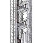
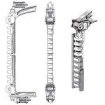
The primary components of Leffler’s electromagnetic system were embedded in the guide rails and car stiles. The guide rails employed a U-shaped metal channel to house “a series of projecting pole-pieces, on which are wound magnetic coils.”[1] The pole-pieces were covered by brass guide-bars that served as the literal guide rails for the car (Figure 2). The sides of the U-shaped channel were fitted with wooden strips that provided a gripping surface for the elevator’s safety device. The counterparts to the guide rail pole-pieces were housed in the car stiles (Figure 3). The stiles also featured two pairs of “flanged guide or keeper rollers. . . carried by sliding yoke-headed plungers,” which were equipped with springs to hold the rollers “tightly against the guide-bars and spring-cushion the car in a central position between the fields.”[1] A third critical component, the commutator, was located on top of the crosshead. Because its operation was directly related to the speed of the car, the commutator’s action was controlled by “means of a rope passing over a sheave, fixed on the rear end of the commutator-shaft, thence over a guide-sheave carried by the rear upper rim of the car, and having both of its ends drawn taut and secured to the building or other fixed support, with one end above, and the other end below the extreme limits of the car’s travel.”[1] The commutator’s operation closely resembled that of contemporary overspeed safeties; thus, his design represented an interesting adaptation of existing elevator technology to a new use.
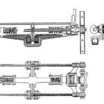
Leffler’s safety device, which he described as a “safety-clutch,” was located under the car. The safety consisted of “two transverse parallel rock shafts or rods, mounted in bearings. . . and provided at their ends with grip-cams or eccentric friction-blocks, which, when released, engaged the wooden facings” of the guide rails (Figure 4).[1] The cams were held away from wooden facings by electrical contacts that kept the safety springs compressed. If the car lost electrical power, the safety would automatically engage. Thus, Leffler’s safety only operated if the power failed. It would not have prevented the car from overspeeding. This apparent oversight was likely due to his belief that his electromagnetic design allowed such precise control of the car that it could not overspeed. He also relied on this system to hold the car in place when was it stopped at a landing. In other words, the car was not equipped with a brake. According to Leffler, when the control lever was in the “stop” position, “the forces of attraction and repulsion (between the field-magnets) would neutralize each other and have no tendency to move the car in either direction.”[1] A full exploration of the detailed operation of this elevator is beyond the scope of this article. However, interested readers may explore this system more fully by examining Leffler’s patent (see this month’s Online Extras).
Whereas Leffler approached his design as an industry outsider who sought to adapt a horizontal system to vertical transportation, his rival was directly connected to the elevator industry. H. Russell Smith (born in 1864) graduated with a BS in Mechanical Engineering from the Stevens Institute in 1888. A native of Chicago, he returned home following graduation and accepted a position with paving contractor J.B. Smith & Co. He began his elevator career in 1890, when he joined the Hale Elevator Co. as an assistant superintendent of construction. In 1894, he left Hale for Winslow Brothers Elevator Co., where he worked as chief engineer. He left Winslow Brothers in 1897, and, following brief periods with Morse, Williams & Co. and Burdett-Rowntree Manufacturing Co., he joined Otis’ Chicago office in 1900. Between 1894 and 1898, he received five elevator patents, one of which concerned an electromagnetic elevator design: “Electric Elevator,” U.S. Patent No. 549,542 ( June 6, 1896).
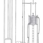
Smith’s patent, with its three images and four pages of text, offers an interesting study in contrast when compared to Leffler’s patent. The latter’s detailed renderings have a visual power clearly missing from Smith’s simple line drawings (Figure 5). However, an examination of Smith’s design reveals a practical scheme predicated on the application of an electromagnetic drive to a standard elevator typology. Smith’s elevator was also the subject of two illustrated articles. The first, “Smith’s Electromagnetic Elevator,” appeared in the December 19, 1896, issue of Western Electrician, and the second, “Ascenseur Electro-Magnétique,” appeared in the April 10, 1897, issue of L’Électricien. The latter was one of the first presentations of an electromagnet drive system to a European audience. (These articles and Smith’s patent have been also included as Online Extras.)
Both articles note that the elevator’s design development phase occurred in Winslow Brothers’ Chicago factory. Work began in late 1895 or early 1896. (Smith’s patent application was filed in March 1896.) Unlike Leffler’s scheme, in which the entire shaft was a part of the drive system, Smith designed an electromagnetic motor that powered the car through a typical shaft. His design was compared to that of a vertical hydraulic elevator, with the “core-piece” of the electromagnetic motor “corresponding to the piston” and the hollow core in which the core-piece traveled “corresponding to the cylinder” of a hydraulic elevator.[2]
The patent drawing also depicted a multiplying sheave, a feature found in hydraulic machines. Like Leffler, Smith designed a brake that relied on an electric coil and plunger magnet, which operated when the electric current was cut off from the brake. However, Smith’s brake (not illustrated in his patent) was controlled by the car control lever, which, when moved to the stop position, activated the brake. The design was also described as capable of being “fully equipped with the improved safety appliances used on the cars of all the hydraulic elevators manufactured” by Winslow Brothers, which included a “simple device located in the car hatchway [that automatically brings] the car to a standstill at the top and bottom limits of travel if not stopped by the operator.”[2]
The Western Electrician article, parts of which may have been written by Smith, summarized the advantages of his design as follows:
“From the point of view of an architect or owner, the electromagnetic elevator has several advantages: requiring no space for the pumps, tanks, pipes and valves of the hydraulic elevator, nor for motor, drum or screw of most electric elevators, it will, if geared two to one and having the core suspended from the overhead beams of the elevator, occupy no space at all, except that required by the car itself…… On account of its peculiar construction, the size and shape of the magnetic motor is such as to occupy in the stories through which it does travel only space about equal to the cylinder body of a vertical cylinder hydraulic elevator.”[2]
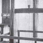
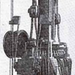
While the confidence expressed in these statements echoes typical advertising hyperbole (and Leffler’s claims in his patent), Smith and Winslow Brothers had a distinct advantage over their competitor. The impetus for the 1896 article was the successful construction of a fully functioning prototype in Winslow Brothers’ factory (Figures 6 and 7). Unfortunately, the photograph, which shows the car platform, “shaft” and motor, does not indicate the elevator’s operational height.
Leffler’s imaginative efforts and Smith’s practical efforts — made real in his prototype machine — represent an intense burst of interest in the adaptation of electromagnets to elevator drive systems. Unfortunately, the challenge of moving beyond concept and working model proved too difficult to overcome, and the pursuit of the electromagnetic elevator was abandoned. Nonetheless, while these early efforts were soon lost to history, their recovery and presentation here serves as a useful reminder that precedents often exist for modern innovations and that the presence of the past surrounds us — if we know where to look.
- Figure 1: Paul W. Leffler’s electromagnetic elevator: car top with front and side car elevations
- Figure 2: Leffler’s electromagnetic elevator: guide-rail drawing
- Figure 3: Leffler’s electromagnetic elevator: car stile front and side elevations and perspective drawing
- Figure 4: Leffler’s electromagnetic elevator: plan, section and side elevation of safety brake
- Figure 5: Smith’s electromagnetic elevator: elevation drawing
- Figure 6: Prototype of Smith’s electromagnetic elevator[2]
- Figure 7: Detail of core, jacketed coils and commutator designed for Smith’s electromagnetic elevator[2]
References
[1] Paul W. Leffler. “Electric Elevator,” U.S. Patent No. 573,820 (December 22, 1896).
[2] “Smith’s Electromagnetic Elevator,” Western Electrician (December 19, 1896).
Get more of Elevator World. Sign up for our free e-newsletter.
