A detailed examination of the unique Eaton & Prince water-hydraulic elevator installed in the Capitol
by Dr. Lee Gray, EW Correspondent
Part one of this investigation traced the specification and bidding process that resulted in Eaton & Prince of Chicago receiving the commission to build a hydraulic passenger elevator for the new Texas State Capitol (completed in 1889)
(ELEVATOR WORLD, April 2020). This article, the last in the series, will examine the type of elevator system installed in the Capitol. However, while based on a reasonable body of evidence, any conclusions as to the system’s design remain speculative due to the fact that the elevator was removed in the early 20th century, and no photos or detailed information on the elevator has been found.
In May 1887, revised specifications were issued for the building’s passenger elevator. The specifications comprise the starting point for this investigation, as they addressed almost every aspect of the system:
“The cylinder shall be horizontal and made of cast iron of sufficient strength, bored out true and well-scoured, forming a perfect and even bearing. The said cylinder shall be 30 in. in diameter and of sufficient length for the height of lift, and, with a water pressure of 45 psi, will lift on the cage a load of 3000 lb, and for every 6 ft of lift, will consume 36.72 gal. of water.
“The guideposts shall be compound and securely fastened to the walls of the well-holes. On the guideposts shall be placed hard maple strips, made true and smooth; all this work [is] to be done in a substantial manner.
“The cage shall be made of seasoned hardwood timber with all the necessary ironwork and braces, neatly painted and arranged for guideposts at the sides of the hatchways, and shall be of proper size to suit the hatchways in the building.
“The cab shall be made in accordance with the original specifications. . . . It shall have a speed of 250 fpm, or less, as desired.
“The weight of the cage shall be counterbalanced by an iron weight attached to the cage or working cable and run in guides made of hardwood.
“The cage shall have four, 3/4-in. in diameter, lifting cables of 8-1/2 T. tensile strength each, and the operating cable shall be 5/8 in. in diameter. The counterbalance shall be connected by two independent 3/4-in. cables. All the cables [are] to be of the best manufacture.
“Two of the cables shall be secured to the cage in the usual manner but shall be sufficiently slack to avoid taking any of the load, in order that their strength may be reserved for an emergency should the regular working cable break.
“The sheaves overhead shall be of heavy cast iron of proper size and firmly supported as required by the original specifications.
“Safety pawls shall be attached to the bottom of the cage and operated by a powerful steel spring. In the event of the parting of the cable or any obstruction in the descent of the cage, the pawls must be so constructed as to securely lock the car.
“An automatic button stop shall be placed on the operating cable for stopping the cage at the upper and lower landings independent of the operator.
“A syphon relief shall be placed on the discharge pipe to stop the piston with the cage and prevent the cables from dropping off the sheaves should the cage become obstructed in its descent.
“Each and all the parts of the elevator and its appliances complete shall be constructed and arranged in a neat, substantial and workmanlike manner, and guaranteed to be free from all defective material and workmanship.”[1]
Information not included in the amended specifications that carried over from the original specifications included the provision of a circular “wrought-iron water tank” located in the attic, which was to be “11 ft in diameter and 5 ft high” with a cistern of similar size in the basement.[2] The elevator operated from the first to the fourth floor and had a rise of approximately 65 ft.
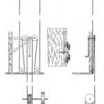
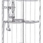
An overall understanding of Eaton & Prince’s response to these specifications is found in an 1889 engraving of its horizontal hydraulic elevator system (Figure 1). The car control system, visible in the cutaway on the right side of the car, appears to be a variation on a design patented by Frederick Prince in 1886 in which the operating lever was linked to the control valve by a system of ropes and pulleys (Figure 2). While the undercar safety is not visible in the engraving, the elevator likely employed a safety similar in design to that patented by Thomas Eaton, Frederick Prince and Joseph Livsey in 1886. This system, however, did not employ the “safety pawls. . . operated by a powerful steel spring” referenced in the specifications. It relied on a modified guide-shoe design: one shoe was fixed and adjusted by a set screw such that it maintained contact with the guide rail. The other shoe was attached to a cam such that it could be forced against the guide rail and the car’s movement stopped by the added friction (Figures 3 and 4).
The safety was activated by a modified flyball governor and clutch system, the speed of which was directly linked to the car’s movement via a safety cable. Its operation was described in the patent as follows:
“As the car descends, the cable operates the pulleys upon the governor shaft, and when the movement of the car is at its ordinary speed, the governor does not expand under the centrifugal action sufficiently to cause contact with the trigger. If, however, the movement of the car becomes more rapid than safety warrants, the revolution of the governor is increased in speed accordingly; and, with this faster revolution, the governor expands until it strikes the trigger and compels it to release the lever. This brings the parts of the clutch together and results in the. . . gripping of the ways by the gibs under the pressure from the cams.”[3]
The use of the term “gibs” rather than “guide shoe” is of interest. While the latter was used in the 19th century, in this instance, the former was a more appropriate choice. Gibs, typically employed in pairs — one fixed and one movable — were used to hold a shaft or connecting rod in place. The designers’ use of this system to convert a guide shoe into a safety device is intriguing.
The hydraulic engine depicted in the 1889 engraving was a push-type machine with a set of fixed sheaves at one end of the cylinder and a set of traveling sheaves attached to a piston at the other end. As the piston pushed the traveling sheaves away from the cylinder, the car ascended; when the sheaves were pulled back toward the cylinder, the car descended. The design of the engine was likely derived from the specifications found in three of Thomas Eaton’s patents (Table 1).
Eaton’s patents primarily addressed improved control-valve designs for standard push-type machines (Figure 5).
Critical questions regarding the first elevator in the Texas State Capitol concern the size of the hydraulic engine and its location in the basement. The original specifications called for a vertical hydraulic elevator, and this appears to have influenced the design and layout of the shaft and adjacent mechanical spaces. In many vertical hydraulic installations, the engine was in the shaft behind the car. The size of the Capitol elevator shaft, approximately 8 X 8 ft, provided sufficient room to accommodate an 18-in.-diameter hydraulic cylinder and an approximately 6-X-8-ft car (Figure 6). However, the shaft was clearly not designed to accommodate a horizontal
hydraulic engine.
The length of a horizontal engine was determined by the elevator’s vertical rise and the number of sheaves employed.
The specifications suggested the use of four hoisting ropes, with two ropes left “sufficiently slack to avoid taking any of the load, in order that their strength may be reserved for an emergency.”[1] The use of “slack ropes” on a horizontal machine would have been problematic, as they would have had a tendency to jump out of their sheaves. Thus, it may be reasonable to assume Eaton & Prince ignored this requirement and employed only two hoisting ropes that ran on four fixed and four traveling sheaves, which meant each rope ran on a total of four sheaves as the piston moved forward and back. This would have resulted in a multiplying factor of four, with the car moving 4 ft for each foot traveled by the piston. With a vertical rise of approximately 65 ft, the total length of the engine would have been approximately 32 ft. If a set of diverting sheaves were placed at the bottom of the shaft, the engine could have been placed outside the shaft (Figure 7). A comparison of the space occupied by the two systems clearly reveals the advantages of the vertical hydraulic engine (which could be considered one of the first machine-room-less elevator systems).
The placement of the elevator engine depicted in Figure 6 is, of course, simply an informed guess. The precise location, size and design of the horizontal hydraulic elevator engine may never be known. In a similar manner, the basis of the statement (found in the specifications) that the engine would use 36.72 gal. of water for every 6 ft. of lift remains a mystery.
While this investigation was successful in identifying the builder of the first elevator and the type of elevator installed in the Texas State Capitol, the need to rely on informed speculation regarding critical details was frustrating. If there is a lesson here, it might be to reinforce the need to fully document old systems prior to their removal (particularly in historically important buildings).
Acknowledgements
Many of my articles have a long arc between conception and realization. In May 2016, I attended a conference hosted by the University of Texas at Austin that included a wonderful tour of the Texas State Capitol led by Stephanie Phillips, a preservation project assistant with the Texas State Preservation Board. Naturally, I inquired about the presence of any historic elevators and was not surprised to find out that the original elevators had been removed in the early 20th century. Not long after I returned home, Phillips contacted me, asking if I could find out who built the original elevators.
Based on the information she had provided (which clearly seemed to indicate that the elevators were Otis Standard Vertical Hydraulic Elevators), I contacted Stephen Showers, the archivist at Otis. Showers, however, found no records of Otis building elevators for the Capitol. I was left with a mystery, which I “parked” to pursue at a future date. In November 2019, Kevin Koch, architect of the Capitol, contacted me, asking the same question Phillips had asked three-and-a-half years earlier. I decided that now was the time to try to solve this mystery. I was
able to complete this investigation thanks to the wealth of information Kevin provided and some diligent (and lucky) research on my part. Life is often best when it’s a collaborative affair. Thank you, Stephanie, Stephen and Kevin.
-

- Figure 1: Eaton & Prince Horizontal Hydraulic Elevator[3]
-
- Figure 2: Elevator control system[4]
-
- The-First-Elevator-in-the-Texas-State-Capitol-Figure-3
-
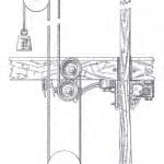
- Figure 4: Elevator safety brake[5]
-
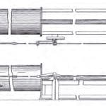
- Figure 5: Plan and elevation of hydraulic push-type engine[6]
-

- Figure 6: Basement plan detail, Texas State Capitol: the elevator shaft is directly below the room at right labeled “water cistern for elevator.” The circle within the white square illustrates the likely location of the vertical hydraulic elevator engine; original image courtesy of the Texas State Library and Archives Commission.
-
- Figure 7: Basement plan detail, Texas State Capitol with the possible location of the Eaton & Prince horizontal hydraulic elevator engine superimposed; original image courtesy of the Texas State Library and Archives Commission
| Patent Title/Number | Application Date | Award Date |
| Hydraulic Elevator”/446.620 | September 20, 1889 | Februry 17, 1891 |
| Hydraulic Elevator”/561.047 | Abril 4, 1890 | May 26, 1896 |
| Hydraulic Elevator”/508.470 | September 26, 1891 | November 14, 1893 |
References
[1] Memorandum of Agreement” (May 30, 1887)
[2] “Building Specifications” (January 10, 1882)
[3] The American Engineer. “Improved Hydraulic Elevator” (July 31, 1889).
[4] Prince, Frederick H. “Elevator,” U.S. Patent No. 335,239 (February 2,
1886).
[5] Thomas W. Eaton, Frederick H. Prince and Joseph H. Livsey, Safety
Brake for Elevators, U.S. Patent No. 347,778 (August 24, 1886).
[6] Thomas W. Eaton, Hydraulic Elevator, U.S. Patent No. 561,047 (May 26,
1896).
Get more of Elevator World. Sign up for our free e-newsletter.


