The Future of Integrated Transport in the Digital Age
Jan 1, 2019
Transportation will morph from a wait-and-catch system to one where on-demand will become ubiquitous.
By Lars Hesselgren, Doguscan Aladag and Rupert Cruise
This paper was presented at ![]() Berlin 2018, the International Congress on Vertical Transportation Technologies, and first published in IAEE book Elevator Technology 22, edited by A. Lustig. It is a reprint with permission from the International Association of Elevator Engineers
Berlin 2018, the International Congress on Vertical Transportation Technologies, and first published in IAEE book Elevator Technology 22, edited by A. Lustig. It is a reprint with permission from the International Association of Elevator Engineers ![]() (www.elevcon.com).
(www.elevcon.com).
The advent of digitally controlled transportation systems will usher in a revolution in how we live in cities. Ultra-high-rise buildings will put far greater demands on intelligent vertical-transportation systems and provide greater opportunities for vertical living. PLP Architecture’s SkyPod system is an illustration of what can be achieved and points toward the complete integration of all urban-transportation systems, such as PLP’s CarTube and UrbanPod. Since presenting at Elevcon 2014 in Paris, further development of the SkyPod system has taken place, and it presents a radical look at the future of vertical transportation. The development includes a proposal for a linear motor system and details the geometric and topological constraints imposed on the system. Digital tools (booking systems and big-data analysis) will ensure the system is on demand, implying no waiting for any passengers.
Future 3D Design of Cities
With increased urbanization, it is likely cities will continue to grow vertically. Current lift technology largely decides the shape of tall buildings.
Increased digitalization and the advent of artificial intelligence (AI) and robotics will ensure that transportation will become far more integrated and be based on “on-demand” and “point-to-point” models. Increasingly, transportation models based on “stations” and “lobbies” will be superseded by systems avoiding, as far as possible, mode changes. Transportation will simply become a service; this is already the model being created around autonomous cars.
Taller buildings also pose fundamental design challenges. Ultratall buildings (1 km plus) will necessarily have quite large footprints, and new fundamental ideas of the shape of buildings will arise. Considering a new approach to building form that takes transportation to the center of tall-building design will better address the potential challenges. SkyPod II proposes a new design methodology for how a transportation-driven, topologically continuous building envelope can be generated where the vertical/horizontal transportation may occur on the building skin.
The Mobility-Driven Building Form
Parametric Model for Topologically Continuous Building Envelope
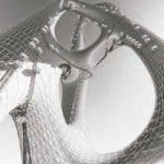
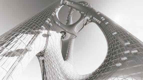
As the form of a tall building is largely constrained by its core, rethinking the nature of vertical transportation in a tall building may also lead to exploration of novel forms and new typologies. Taking vertical transportation and its spatial and operational efficiency to the center, SkyPod II proposes a new way of composing building form. It suggests that the tall-building form acts as a network with a continuous topology, upon which building skin can be used for vertical/horizontal transportation (Figure 1). In other words, mobility becomes the main factor driving the form of the tall building. To develop a design methodology for this new proposed typology, a parametric and multistep strategy is proposed and developed using an algorithmic modeling editor embedded within the 3D modeling software McNeel, Rhinoceros. [6]
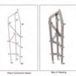
The first step (Figure 2) for the form is to establish the positions and number of main lines/vertical axes that always connect at the top. These form the main spines of the network topology and may suggest different uses for the parts of the tall building (e.g., hotel, office, amenities, etc.). The second step (Figure 2) is that, on these main lines, a certain number of points (nodes) and the connectivity relationship between those points are determined by the designer. The position/number of the nodes may suggest where and how much the designer wants the main lines to be in contact with each other. A 3D network topology is formed at the end of this step. The third step (Figure 2) is to generate a continuous, high-resolution mesh from this line network, which will give us the base geometry for the envelope of the building. The nodes of the network are solved as convex hulls, and hulls are stitched together using polygonal struts. In this case, the exoskeleton[6] component is used to perform the convex hull meshing operation in Grasshopper. As the fourth and last step (Figure 2), the low-resolution mesh obtained from the line network is subdivided and smoothed to conform with the minimum surface curvature requirements and provide topological continuity. In this case, a topological mesh editor add-on for Grasshopper is used to perform mesh subdivision and smoothing operations.[13] The underlying algorithm for mesh subdivision is Loop subdivision[9] and the Laplacian smoothing algorithm for mesh smoothing.[7]
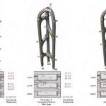
Having established a new parametric form-generation methodology, the designer can easily obtain different building forms driven from different network topology preferences. In Figure 3, three different topologically continuous mesh envelopes are shown based on the same main-line condition but having different node positions and connectivity relations as a demonstration of how the parametric algorithm can output different forms.
Track Formation on Continuous Mesh Envelope
The efficiency of laying out the track system is crucial for the efficiency of the overall building transportation system. A two-step process is developed to geometrically determine the most-efficient track layout, which has access to all floors of the building but also always uses the shortest path when traveling on the building envelope. The process takes the previously generated high- resolution mesh envelope and network nodes determined by the designer as inputs and outputs a shortest-distance network linking all network nodes mapped on the faces of the envelope mesh. The first step (Figure 4) is to identify the closest points on high- resolution envelope mesh to all network nodes. The second step is to connect every node to every other node in the network on the mesh topology as straight lines and remove the overlapping lines within the network to obtain nonrepetitive connection lines between network nodes. Following that, unique straight lines connecting nodes are mapped and regenerated on the envelope mesh as shorted distances using the ShortestWalk component in Grasshopper. In the second step (Figure 3), the obtained shortest distance curve network is again smoothened according to minimum curvature requirements of the track geometry, and switches are generated at the intersections.
The resulting curve network (Figure 4) provides a geometrical basis for the centerline of the rather complex track geometry. The mesh face normal at the point closest to a track center curve point would give the track normal plane at that track center curve point.
Overall, the developed parametric algorithm outlines a seamless process of derivation of a topologically continuous mesh geometry based on designer input data, along with a shortest-path track line network mapped on the mesh between designated network nodes (Figure 4).
SkyPod II Design
Today, the default assumption in tall-building design is that a central lift shaft provides both vertical transportation and one centrally located primary structural support. The capacity of the normal lift system is restricted by the topology of the system: each shaft will contain one (sometimes double-storied) cabin. The taller the system, the emptier the lift shaft.
The first assumption the SkyPod II challenges is that the shaft is one-directional. This topology has been abandoned by all transportation systems except lifts: roads, railways and all variants thereof use one-way tracks to increase capacity. These types of tracks are currently under consideration for some lift systems. The SkyPod employs a one-way track system, and this topology ensures that the longer the track, the more vehicles can use it. The system is based on a track system that is standardized to accommodate a range of pods. This is like other transport systems, such as rail and road.
The track system incorporates the propulsion mechanism, which is a linear magnetic system. The active magnetic system is incorporated into the track; the fixed magnets are part of the transport bogie. Unlike train tracks and roads, the SkyPod II track is designed to be completely versatile in 3D. The track can take any orientation, from vertical to horizontal, and crucially allows change of plane. It is fully switched so that any complex topology can be implemented. For such a system to work, it has to have two degrees of freedom within the transport pod. One degree of freedom systems is common, such as the pods on the London Millennium Wheel. Systems with two degrees of freedom are generally suspended systems, such as ski lifts. The SkyPod II system approach is that a stable system — such as a lift — is far preferable from a comfort point of view and is, therefore, adopted as a design principle.
Track System
The dimensional constraints on any track system are crucial. The two critical dimensions for the track are track width and curvature. The track width is determined by the pod configuration. To allow maximum flexibility, it is vital that a rear door can be used on any pod configuration when the track is in a vertical configuration. Since the orientation of the track when on a vertical trajectory can be on any vector, the critical dimension is determined by the circle circumscribing a standard door. For the current design, that dimension is a 1-m-wide by 2-m-high rectangle, which gives a radius of 2.3 m. The track curvature in any plane determines the geometry of the fixed magnets attached to the bogie. For the system to be useful in realistic tall-building design, this has to be relatively tight. For design purposes, this has been set at a 5-m minimum radius. This radius in turn coupled to the tolerance of a maximum of 5 mm between fixed magnet and track to determine the maximum length of the fixed magnet at 220 mm (Figure 5).
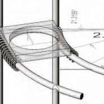
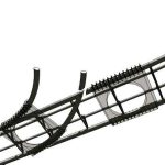
For the typical design, this translates into 200-mm-long fixed magnets kept in place by triple sets of wheels at 240-mm centers (Figure 6). Since these magnets are physically linked, they typically behave as the familiar Slinky shape. Prototype linkages are currently under design, as are the joints for the triple sets of wheels to the bogie.
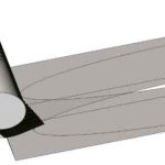
This radius also determines the general layout of switches within the system. The design of the switches incorporates no moving parts. Instead, the pattern of magnetic flux steers the bogie into one of the two tracks (Figure 7).
The switches need not lie on a plane; it is sufficient that all the track parts lie on a common smooth surface with a minimum curvature of 5 m. The track can also be helical, which allows a change of plane that naturally induces torsion (Figure 8).
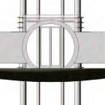
The track section is currently assumed to be a circle such that the three-wheel configuration can rotate around the track when the track geometry is in torsion (Figure 9). The diameter is set to 300 mm to provide adequate surface for the magnetic interface. (See section on design of linear motor.) Since a track clearance of 2.9 m is required, the center-to-center distance is 3.2 m.
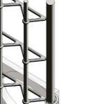
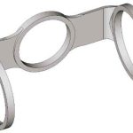
The circular track will need a support system such as the typical example shown in Figure 10. This truss would allow rear entry when the track was completely vertical (Figure 11). Many other variants are possible, including the fixing of the track to adjacent structures, as would often be the case on building structures.
Pod System
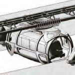
Pods come in different sizes. The load-bearing capacity of the linear motor is of the order of 4.8 mT. We are illustrating the largest pod (the MaxiPod), which is capable of lifting a car. The two degrees of freedom is achieved by a rigid connection between the three ring-bearing components (Figure 12).
The pods will arrive at different types of stops. At high-capacity stations, there will be loading from either end. This arrangement would include the ability to load vehicles (UrbanPods) directly into the MaxiPod (Figure 13).
SkyPod II Booking and Flow Optimization System
The reconfiguration of a lift system into a topologically rich system, like terrestrial roads and railway systems, means that techniques being developed for those systems will be available to the SkyPod II system.
In the future, transportation will morph from a wait-and-catch system to one where on-demand will become ubiquitous. Those developments will also mean that direct point-to-point systems (such as cars, taxis and ride-sharing systems) will become the accepted norm.
We can, therefore, expect that the SkyPod II system will include predictions from big data to optimize pod locations and movements. Modern lift systems do this to a limited degree but are not focused on integration with larger systems. In addition, big data will also be personalized such that the system will anticipate individual movements. Your mobile phone will simply say, “The usual trip?” and you will respond, “Yes.” This will ensure there will be a SkyPod waiting, whether you arrive on foot, by bike, on a public-transportation system or, ultimately, in an UrbanPod that seamlessly takes you to your floor in a 1-km-high tower.
In effect, the AI will know you better than you know yourself, and the SkyPod revolution will change not just architectural design but the way we think of transportation — from a painful experience to one that is just a service.
Linear Motors
A Brief History of Linear Motors
Wheatstone designed the first linear motor in 1841, just 10 years after Michael Faraday’s discovery of electromagnetic induction.[5] Since then, until the 1960s, there has been relatively little development in the field of linear motors, compared to that of the rotary motor. This was mainly due to the perception of engineers that rotary motion was the most efficient way to convert electrical energy to mechanical energy or vice versa.[8] With advances in magnet technology in the 1990s, there has been an ever-increasing number of applications for linear motors, from high-speed magnetically levitated transportation[2] to ropeless mine hoists. [3]
More recently, a German magnet manufacturer announced a significant breakthrough in magnetic materials. [10] Vacuumschmelze GmbH & Co. managed to significantly increase the magnetic properties of samarium-cobalt (SmCo) magnets by a phenomenal 34%. This is proving to be a “gamechanger” for linear motors, as the main advantage is that SmCo magnets have a much higher operating temperature of 350°C, whereas neodymium-iron- boron magnets typically used in linear synchronous motor (LSM) designs have a much lower operating temperature of 120°C.
Advantages of Linear-Motor Propulsion
A key benefit of using linear motors is their robustness and reliability. Linear motors are now an established technology and have been working continuously in some very harsh conditions for 20-30 years with very little maintenance. In one application, they have been exposed to extreme weather conditions for 17 years and are still operating normally. In another application (an amusement park ride), the linear motors are completely submerged underwater. Also, since thrust is produced electromagnetically, there is no transfer of power through a mechanical interface. This results in less wear and tear, no traction issues and lower mechanical losses, since the guidance track can be lubricated. Importantly, because mechanical traction is not required, there is no limit to the achievable gradient.
Moreover, linear motor technology allows for system-level improvements in efficiency and redundancy. Contributing to this is that the motion of each pod can be individually controlled. Also, adopting a modular design for the linear motor’s track and drive arrangement makes it easy to swap out a faulty unit, and, if designed accordingly, the system could continue operating with the failure of any individual section.
Linear Motor Design
The main aim of the motor design procedure is to maximize the thrust force, while minimizing the size of the linear motor. The fundamental high-level motor design equation is:
F = BQA (Equation 1)
where F is the force produced, B is the magnetic loading, Q is the specific electrical loading, and A is the air-gap surface area.
Since the thrust force is directly proportional to the air-gap surface area, to double the force, it is either necessary to double the width of the stator windings and the magnet plate or to double the length of the magnet plate.
The smaller the air gap between the magnet plate and stator, the larger the magnetic loading (and, hence, thrust) that can be achieved per air-gap surface area. However, the air-gap size is ultimately constrained by mechanical considerations.
Similarly, the higher the current in the windings, the higher the specific electrical loading and, so, the greater the force produced. This is limited by thermal considerations. So, a higher electrical loading can only be achieved with improved cooling or a lower duty cycle.
In addition to the thrust force, there are also normal and stabilization forces between the magnet plate and stator. The normal force is the force that occurs due to the permanent magnets being attracted to the stator core. It can be an order of magnitude larger than the thrust force and has a direct impact on the design of the mechanical guidance arrangement. The stabilization force is the force that tries to keep the stator and magnet plate aligned.
However, for an LSM, this force component is negligible in comparison to the thrust and normal forces. So, when using a guidance system, the stabilization force is not a significant design consideration.
Motor Configurations
There are three main types of linear motor configurations, namely:
- Single sided: This consists of one section of stator windings and one magnet plate.
- Double sided: Usually, this consists of two sections of stator windings, which are positioned on both sides of the magnet plate.
- Tubular: A tubular linear motor is formed by rolling a flat linear motor around the longitudinal axis. In general, the stator windings completely encircle the magnets, and the magnet plate is cylindrical.
The tubular design has advantages over that of single and double-sided LSMs:
- It has high force densities due to its cylindrical topology.[12] Due to the geometry of the tubular topology, the magnetic flux is concentrated toward the center of the motor.
- The coils are also completely cylindrical, so there is no overhang. This ensures optimum use of the copper and stored energy.[4] Note that the winding overhangs significantly increase the total cost of linear motors with long tracks of primary windings.
Initial Design of the Linear/Tubular Motor for the SkyPod II System
A modified tubular LSM is proposed for SkyPod II. It is a tubular linear motor with a gap along the length of the linear motor to allow access to the stator windings (Figure 6). Due to this modification, this type of linear motor is not restricted in terms of its length and is seen as an ideal model for linear-motor applications with long travel distances, such as elevators.
The proposed modified tubular motor design is a unique type of linear motor and original in terms of its design and construction. It differs from previous modified tubular designs[11] in that the magnets partially surround the primary windings.
A quick check of the feasibility, with a few rough calculations based on the dimensions of the system and an analysis of the peak performance characteristics of different linear motors, shows that the proposed modified tubular design produces a continuous rated thrust force of 60 kN. The continuous rated thrust can be increased for short periods by 150%. Therefore, the modified tubular motor is capable of lifting and accelerating the proposed 4.8-mT load.
High-Level Control Considerations
LSMs are powered and controlled by the same type of power electronic motor drives used for rotary motors. Hence, the proposed tubular motor design uses standard off-the-shelf hardware components available from a wide range of motor drive manufacturers. Proprietary linear motor control algorithms and stator section switching strategies enable these motor drives intended for rotary motors to drive the modified tubular synchronous motors with an additional semiconductor switching layer used between the tubular motor sections and the motor drives efficiently and accurately.
A useful feature of this permanent-magnet tubular motor is that it inherently exhibits passive failsafe braking.[1] Thus, in the case of a power failure or fault condition, the speed of the pods would be limited to a slow terminal velocity. This is achieved by using normally closed relays to short out the stator windings whenever they are not energized. When the magnet plates on moving pods interact with stator sections with shorted windings, currents are induced in the windings that, in turn, cause a magnetic field that opposes the motion.
- Figure 1: New tall-building typology in which the building envelope is used for transportation
- Figure 2: Steps for generation of a topologically continuous mesh envelope
- Figure 3: Three different building envelope mesh outputs based on different node positions and connectivity relation
- Figure 4: Two steps for generation of shortest-distance track layout on envelope mesh with inputs and track centerline output
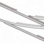
- Figure 5: Minimum radius of 5 m determines length of fixed magnets.
- Figure 6: Isometric of 12 fixed magnets with triple sets of wheels on 300-mm-diameter tube
- igure 7: The magnetic pulse is interrupted on the left track to go straight (solid arrows). To turn right, the field is activated on the turning track (white arrows) and off on the straight track
- Figure 8: Underneath view of track with bogies with helical transformation (top right)
- Figure 9: Arrangement of magnets when track is in torsion
- Figure 10: One configuration of truss support
- Figure 11: Door entry through truss (in context of MaxiPod)
- Figure 12: Three perpendicular bearings allowing two degrees of freedom of movement/rotation
- Figure 13: UrbanPods entering and exiting MaxiPods via adjacent platforms
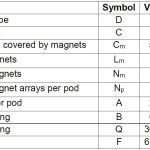
- Table 1: Initial high-level design of the modified tubular motor for SkyPod II
References
[1] Bodika, N. (2005) Modelling of a Permanent Magnet Linear Synchronous Motor Under Regenerative Braking. MSc(Eng) Thesis, University of the Witwatersrand, Johannesburg.
[2] Central Japan Railway Co. MLX01 Maglev eXperimental 01 Japan (1998).
[3] Cruise, R.J.; Gore, V.; and Landy, C.F. “Economic Considerations of Linear Synchronous Motors in the South African Mining Industry,” The Second International Symposium on Linear Drives for Industry Applications, p. AP–20:86–89, Tokyo, Japan, April, 1998. The Institute of Electrical Engineers of Japan.
[4] Copley Motion Systems (2003) (www.copleycontrols.com/motion/ technologies/motor, accessed July 2003).
[5] Gieras, J.F. Linear Induction Drives. Oxford University Press Inc., New York, ISBN: 0198593813 (1994).
[6] Grasshopper (2018) (www.grasshopper3d.com/group/exoskeleton, accessed February 13, 2018).
[7] Herrmann, L.R., “Laplacian-Isoparametric Grid Generation Scheme,” Journal of the Engineering Mechanics Division, 102 (5): p. 749–756 (1976).
[8] Laithwaite, E.R. “Linear Electric Machines – A Personal View.” Proceedings of the IEEE, Vol. 62, No. 2, p. 250–290 (February 1975).
[9] Loop, C. Smooth Subdivision Surfaces Based on Triangles, M.S. Mathematics Thesis, University of Utah (1987).
[10] Vacuumschmelze GmbH & Co. Improved Sm2Co17 Alloy for Advanced High-Performance Machines. Hanau, Germany (October 2017).
[11] van Zyl, A.W. Design, Construction and Evaluation of a Modified Tubular Linear Synchronous Motor. Johannesburg, South Africa (March 2006).
[12] Wang, J.; Jewell, G.W.; and Howe, D.A. “General Framework for the Analysis and Design of Tubular Linear Permanent Magnet Machines.” IEEE Transactions on Magnetics, vol. 35 Issue 3, p. 1986–2000 (May 1999).
[13] Weaverbird. (www.giuliopiacentino.com/weaverbird, accessed February 13, 2018).
Get more of Elevator World. Sign up for our free e-newsletter.
