The Future of the Elevator Safety System
May 1, 2017

An examination of technology that can bring the safety of elevators to the next level
This paper was presented at  Madrid 2016, the International Congress on Vertical Transportation Technologies, and first published in IAEE book Elevator Technology 21, edited by A. Lustig. It is a reprint with permission from the International Association of Elevator Engineers
  (website: www.elevcon.com).
Today’s safety system of elevators has not been changed in many years. What had been changed are the applications. Buildings now reach 1 km in height, which puts high demands on safety components such as the overspeed governor and safety gear. On the other hand, modernization is still one of the most important businesses and not only in Europe. Space requirements and functionalities are the challenges.
The Wittur Group, as an elevator-industry key player for safety components and safety systems, is active in creating new products. Safety gears that do not need a conventional mechanical overspeed governor is one such solution. Safety levels and functionalities need to be considered in another way.
The elevator world is also working on other new concepts, like multiple cars running in hoistways not purely vertical and powered by electromagnetic drives. This requires a complete revolution of the safety system. One key product would be an electronic safety brake on the car, which would need to follow norms and regulations.
1. State-of-the-Art Technology of the Safety-Gear System
The safety system of an elevator consists of a variety of different mechanical and electrical components responsible for the safety of the passenger, maintenance personnel and lift system itself. In terms of risk for people inside the car, the following components are essential:
- Motor brake — to hold the car at landing and brake the car in an emergency
- Safety gear — to stop and hold the car from overspeed or in a freefall
- Buffer — to absorb the impact energy
- Safety switches — to open the safety chain
Modern elevators have, besides these, further safety functions, such as against uncontrolled movement (UCM) away from the landing floor with the doors open, which is partially realized with the same components as listed above.
The safety-gear system itself consists of several mechanical components:
- Safety gear (instantaneous or progressive type)
- Mechanical synchronization of the safety gears
- Overspeed governor
- Overspeed governor rope
- Tension device of the rope loop
- Linkage between the governor rope and the synchronization
The disadvantages of the current system are not only the large number of components and their reliable mechanical interaction. Another aspect is the high installation cost. Also, lack of maintenance represents a high risk potential, which can compromise their reliability. Apart from the above-mentioned disadvantages, the huge space requirement of the components is an issue that plays a considerable role, especially in modernization.
2. Mechatronic Impact on Safety Gear
2.1 The Concept of an Electromechanical Safety Gear
Mechatronic safety components and systems are utilized in many industrial machines. By transferring these elements to today’s entire mechanical safety-gear system, it can be simplified and, therefore, improved. The following describes both the benefits and challenges of such a system.
The task of the governor system is to activate the safety gear at overspeed. The comparable mechatronic approach is to trigger an actor (magnet) on an electromechanical safety gear via safety electronics and corresponding sensors.
Such a system substitutes the overspeed governor, as well as the rope loop and its tension device. The safety electronics are integrated in the elevator control and cuts, among others, the safety circuit at overspeed. Simultaneously, the sensor (e.g., magnetic tape encoder) can be used for car position information.
2.2 Design of an Electromechanical Safety Gear
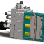
The principle of the patented design is based on a roller safety gear with adjustable spring force. The roller is lowest in its initial position. The actuating spring, which is designed as a compression spring, is held tensioned by a magnet. If the magnet falls, the spring presses the roller against the guide rail, and this runs independently up to its final position. The engagement of the roller is carried out mechanically by the spring, which is held electrically tensioned. Considering that, the safety gear can be assumed as compliant with EN 81. The actuating spring is fully compressed during the safety gear’s gripped situation. The reset of the safety gear is done by simply lifting the car. The magnet needs to be powered beforehand in order to secure the guide plate in its normal position.
EN 81-20 Chapter 5.6.2.1.5: Electrical Checking describes the general requirements in terms of stopping the machine after safety-gear engagement. Because there is no mechanical synchronization anymore, a separate safety switch for each device has been foreseen. Tests have shown that, with appropriately designed magnets, the electrical synchronization is more responsive than mechanical synchronization. This is another advantage in terms of uneven loading of the car.
The failsafe concept requires a battery backup (UPS) to avoid unintentional engagement.
3. Potential of More Electronics in Elevators
The introduction of Programmable Electronic Systems in Safety Related Applications for Lifts (PESSRAL) as normative amendment in EN 81 enables the use of electronic components to design safeties. It is based on the international norm IEC 61508: Functional Safety of Electrical/Electronic/Programmable Electronic Safety-Related Systems.
3.1 Integration of an Electromechanical Safety Gear in an Elevator System
Sensors and safety electronics are required to release new components like GLGS-22U. Such components are available on the market already.
An important aspect of more electronics in elevators of the future is monitoring. As a result, anytime the condition of the lift or of certain important components are checked, preventive measures to enhance security can be set. This leads to new components, and the elevator (as well as the business) will change.
Considering usage of further advantages of safety electronics (for instance, realization of the shaft end-limit switches), a series of signals needs to be provided to such safety electronics to ensure lift functionalities such as inspection drive and recall drive. An additional simplification can be achieved by use of safe CAN fieldbus.
What needs to be noticed when applying GLSG-22U is the issue of emergency evacuation (for example, in a power-loss situation). In such a case, the movement of the car is only possible in the upward direction.
If such an electromechanical safety gear is constructed in double-acting form (including upward braking) considering appropriate guidelines and measures, it can also be used in lifts according to EN 81-21: New Passenger and Goods Lifts in Existing Buildings with regard to realizing the safety space in both directions.
3.2 Advantages
There are a lot of advantages when using such a new safety gear:
- Fewer components (space allocation, functional risks, reduced cost on installation and service, etc.)
- Simple integration to the car slings
- Simplified multiple arrangement of GLSG-22U (e.g., four units electrically synchronized)
- Real-time synchronization
- No negative influences to the system from, e.g., travel height
- No hazardous speed from inaccuracies in the speed-limiter system
- Self-monitoring system recognizes critical situations (higher safety).
- Arrangement of several cars in one shaft (easier to implement)
Thinking on the next level of safety systems, keeping in mind the opportunities electronic can offer, one consequence would be a safety brake with controlled brake force that combines all the needed functionalities into one component:
- Controlled deceleration (minus brake force) at freefall, overspeed in the up or down direction, emergency stop, emergency terminal slowdown and UCM
- Holding brake at landing (no releveling required during loading)
- Automatic rescue function — braking the car “smoothly” and exactly at a defined landing
Positioning such a brake directly on the car would increase the safety level for the passenger, especially in traction elevators, because there exists a certain risk of traction loss, which, in a worst case, leads to fatal accidents (UCM).
Another aspect is a high deceleration, which can occur when braking a car (with the motor brake), which is suspended, for instance, with a tooth belt or another high-traction means, due to the fact that there is reduced slip on the traction sheave. Dangerous deceleration (> 1 g) also happens when there is not a fully loaded car (only one person in the car), and the safety gear grips.
Increasingly, architects wish to realize buildings that do not have a purely vertical shape. Such demands need rope-free elevator solutions (driven, e.g., by a linear motor). Multiple cars may run criss-cross through the same shafts. The safety concept behind such an elevator needs a brake positioned on the car directly.
4.1 Concept of Covering Functionalities in Another Way
In the Annex III: List of Safety Components for Lifts of the Lift Directive 2014/33/EU, point 2 is prescribed a device that prevents the car from falling or UCMs (referring to point 3.2 of Annex I: Essential Health and Safety Requirements.) Furthermore, in Annex I, Chapter 3: Risks for Persons in the Car, it’s defined to have a device which, in the event of a power cut or failure of components, prevents the lift from freefall or UCMs.
The brake force of a safety gear compared to other brakes acting only in the elevator roped condition is extremely high. Due to the fact that the brake force (which is not now controlled) applied is much too high compared to the current unbalanced mass between car and counterweight, passenger injuries when activated in an event of overspeed can occur. On the other hand, the event of freefall is, in practice, luckily very seldom. Considering the above statements and the possibility of preventive monitoring of safety components before the fail, the event of freefall of the car can be excluded. The consequence is that the required brake force of a car safety brake will be reduced significantly (likely more than 40%). This also means that the design of this brake is more compact.
Following this concept and the possibility of technically ensuring functional safety to high standards based on IEC 61508, the Lift Directive may need revision in the future.
As buildings already reach 1 km in height, there are associated technical challenges for safety components. The rated speed of such elevators is at least 10 mps. The EN 81 defines braking speeds of about 115% of the rated speed, which gives a different impression on hazardous speeds in elevators.
Sensors and monitoring, combined with the opportunities safety electronics can offer, will bring the safety of elevators to the next level.
4.2 Advantages of a Controlled Car Brake
Such a brake concept on the car clearly improves safety based on the following summarized advantages:
- The car is kept steady in a level position (UCM is excluded.)
- Greater passenger safety (controlled deceleration in any situation)
- Permanent self-check-routines system (safety improvement)
- Preventive-maintenance opportunities (24/7 remote monitoring)
- New architectural possibilities (combined vertical and horizontal shafts — multiple cars)
- The reliable functionality is not affected by travel height.
- Fewer components
- New features (automatic rescue procedures)
5. Conclusion
The integration of more mechatronics in elevators is a necessity. The capabilities in terms of increasing the safety level for passengers must be seen as a chance. However, the norms and directives need to consider these possibilities and the comprehension, and knowhow about such new components must be taught in the lift industry.
More sensors in elevators will change the components’ looks and functionalities. Therefore, service and maintenance concepts will also change. The communication level of the single components and their interoperability via fieldbus technology are key and will help forming the intelligent elevators of the near future. Safety concepts, including controlled safety brakes, are needed to cover these requirements and new functionalities.
-
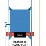
- Figure 1: The modern safety system (schematic)
-
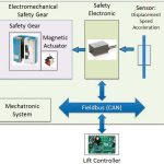
- Figure 2: Mechatronic concept of a safety-gear system
-
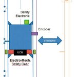
- Figure 3: New safety system (schematic)
-
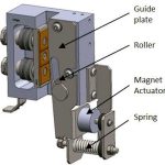
- Figure 4: Wittur GLSG-22U
-
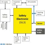
- Figure 5: “Safety Electronic” from PESSRAL
-
- Figure 6: Wittur concept study of a controlled brake
-
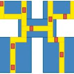
- Figure 7: Scheme of a building not purely vertically oriented
-
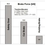
- Figure 8: Brake force comparison
References
[1] Nitidem, E. “Innovative Control-by Wire Technology for Elevator Safety” VFA Presentation, Interlift Augsburg (2015).
[2] Kriener, K. “Neue Spielräume am Beispiel einer elektro-mechanischen Fangvorrichtung” (2015).
[3] Heilbronner Aufzugstage (2016).
Get more of Elevator World. Sign up for our free e-newsletter.


