The Hocquart Escalator in the Gare d’ Orsay
May 1, 2018

Many details on an early high-profile escalator are uncovered.
The June 1908 issue of the French transportation engineering journal Revue Générale des Chemins de Fer et des Tramways included an illustrated article on an escalator recently installed in the Gare d’Orsay, a train station/hotel complex built by Compagnie d’Orléans, one of France’s private railway companies. The train station opened in mid 1900 to serve the crowds that came to Paris to attend that year’s Exposition Universelle World’s Fair. The article’s author, Charles Jullien (1863-1952), was the chief transportation engineer for the Compagnie d’Orléans, and he provided a detailed account of the construction of the new escalator. This account, coupled with the article’s numerous illustrations (10 drawings of individual components, one transverse section, one longitudinal section, one plan and two photographs) permit an unusually thorough investigation of an early escalator.
In late 1907, the Compagnie d’Orléans decided to replace the main stairway used by arriving passengers with an escalator. This decision was predicated on alleviating congestion that occurred when multiple trains arrived at the station. Interestingly, the company apparently only installed one escalator, intended solely for arriving passengers. The company evaluated three different systems: Jesse Reno’s inclined elevator, Otis’ escalator (the design of which the Compagnie d’Orléans attributed to Charles D. Seeberger) and a system designed by French engineer Édouard-Louis Hocquart. Reno’s design was rejected, because the company felt that passengers should travel on steps that featured “an absolutely horizontal plane.” The company viewed horizontal steps as an aid to travelers with luggage, as they could place their bags on the steps while riding.
Otis’ escalator was also rejected. In the early 1900s, this system often employed long horizontal moving-walk features at the top and bottom of the escalator (Figure 1). Because the Compagnie d’Orléans was replacing existing stairs, they determined there was insufficient space to accommodate the Otis machine. It was also the most expensive. Hocquart’s system met the company’s needs, and it was designed and manufactured in France, facts that doubtless appealed to the company’s sense of national pride.
Jullien appears to have been directly involved in the escalator’s installation. And, although the origins of the detailed drawings that accompanied his article are unknown, their detailed dimensions give the appearance of working drawings or construction documents. Jullien’s description of the system began with the steps, which followed the established paradigm of employing nonslip treads that meshed with combplates at the top and bottom of the stairway. However, the actual step design and its manufacture were unique. Hocquart used a modular system that allowed him to easily build steps of almost any size. The primary component was a relatively lightweight, slender, step-shaped unit, which was divided into two halves: the lower section (28 mm thick) included holes for the wheel axles, while the upper section (20 mm thick) formed part of the tread (Figure 2). This section included a shallow “dovetail recess” designed to hold the tread material.
The construction of a typical step involved setting two 65-mm-diameter steel tubes vertically into a frame such that their positions matched the openings in the step components. The height of the tubes equaled the desired stair width. The number of step components required for a given stair width were threaded onto the vertical tubes. This simple process was complicated by Hocquart’s design, which required a 2-mm separation between the base of each step component. This separation at the base produced 10-mm wide “grooves” at the level of the step treads. The frame that supported the vertical tubes facilitated this required separation. The frame was also designed such that the tubes were centered in the holes of the step components, with a 4-mm gap surrounding each steel tube. As each section was threaded onto the vertical tubes, “foil rings” were placed in the 2-mm gap between components. This step was necessary, because once all the components were assembled, these gaps around the support tubes were filled with cement (Figure 3). According to Hocquart, the cement provided “a very great adhesion between the various elements.”
After the cement had hardened, the step was fitted with guide plates. These featured two 55-mm diameter flanged bushings designed to fit snugly into the step support tubes. The bushings were sized to support the 34-mm diameter axles that carried the step rollers. The guide plates also featured bars that ensured “the guiding of the steps along two brackets assembled to beams” (Figure 4). The final step was to fill the dovetail recesses with a mixture of cement and carborundum, with the hardened material extending approximately 2 mm above the recesses. Carborundum (carbon and corundum, also known as silicon carbide), was formulated in 1891 by Edward G. Acheson and originally intended for use as an industrial abrasive. By the early 20th century, it was also used for step treads in high-traffic areas, such as train stations, because of its durability. The Gare d’Orsay escalator steps employed 50 sections, and the finished steps were 1.5 m long.
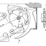
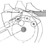
Each step featured pairs of front and rear rollers. The front or driving axle extended beyond the rollers and was attached to the drive chains (Figure 5). Hocquart used a Galle chain to drive his system. Invented by French artist André Galle (1761-1841) in 1829, it is typically described as one of the simplest types of steel link chains, in which the plates rotate directly on the pin lugs. The resulting chain has a very small bearing area, and modern standards recommend an operating speed not exceeding 18 mpm. The top and bottom of the stair featured cams located on each side of the escalator that guided the steps on their journey (Figures 6 and 7). While Hocquart typically installed his system such that the step tread exited the upper landing in a horizontal position, Compagnie d’Orléans asked for a design modification. The upper cams were modified to give the steps an upward tilt or inclination during their passage through the combplate. This was intended to aid travelers in exiting the stairway and “automatically deposit” them on the landing (Figure 8). The lower combplate was also unique. It resembled a shallow (85-mm-high) step to indicate to passengers where they should place their feet when entering the escalator (Figure 6).
The final aspect of the system described by Jullien was the moving handrail (Figure 9). The handrail’s intricate design followed the pattern established in the step assembly. The driving portion was composed of two steel bands separated by a flexible wooden furring strip. The band was fitted with small steel plates, placed at 250-mm intervals, which provided bearings for bronze guide cleats, which were riveted to the steel plates. A canvas covering was glued to the moving band assembly to “ensure its solidarity.” The rounded handrail carried by this assembly was made of agglomerated cork, produced in 1-m-long sections, which were attached to the traveling band by a second glued canvas covering. Transverse shallow vertical cuts in the cork were made every 5 cm, and the cork was finished with a velvet covering that was glued to the flat surfaces and tapped (unglued) into the vertical cuts. The bronze guide cleats traveled in a wooden slide, and power was transmitted to the handrail via a gear mounted at the top of the escalator and driven by a chain attached to the driveshaft.
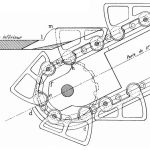
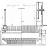
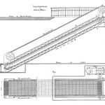
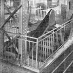
The transverse and longitudinal sections, plan and photographs included with the article offered an effective visual summary of the Gare d’Orsay escalator (Figures 10-13). An operational summary was provided in the article’s conclusion, which focused on the system’s efficiency. The escalator was powered by a 15-hp, shunt wound motor with a geared connection to the driveshaft. The maximum operating speed was 30 mpm; however, the typical operating speed ranged from 20 to 22 mpm. Upon its completion, the Compagnie d’Orléans reported that the escalator had improved the flow of passengers from the arrival platforms up to the main station. Using data gathered before the installation, the company reported the following comparison: during a period of 244 min., which saw the arrival of 32 trains, 8,072 passengers (33 per minute) climbed the original 1.8-m-wide fixed stairway. During a period of 202 min., which saw the arrival of 50 trains, 11,072 travelers (59 per minute) were carried upward by the 1.5-m-wide escalator.
Charles Jullien’s 1908 account of Hocquart’s escalator reveals the challenges associated with developing new transportation systems, as well as the idiosyncratic characteristics of these early designs. The use of cement to “bind” the step components into a cohesive whole and the mixture of cement and carborundum used for the treads, in addition to increasing the step’s weight, raise questions about the system’s constructive logic. Nonetheless, the complexity of the overall solution effectively reflects the inherent complexity of what, to the untrained eye, appears to be a simple, effortless and almost magical continuous movement of steps that aid a weary (or impatient) traveler along their way.
-
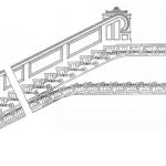
- Figure 1: Otis escalator, circa 1902
-
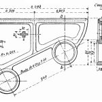
- Figure 2: Hocquart escalator step component, Gare d’Orsay, 1908
-
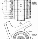
- Figure 3: Hocquart escalator step assembly, Gare d’Orsay, 1908
-
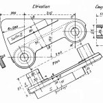
- Figure 4: Hocquart escalator step guide and end plate, Gare d’Orsay, 1908
-
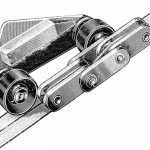
- Figure 5: Hocquart escalator step guide and end plate, Gare d’Orsay, 1908; edited by your author; original drawing by Louis Poyet
-
- Figure 6: Hocquart escalator, upper landing section, Gare d’Orsay, 1908
-
- Figure 7: Hocquart escalator, lower landing section, Gare d’Orsay, 1908
-
- Figure 8: Hocquart escalator, upper landing section showing action of tilting step, Gare d’Orsay, 1908
-
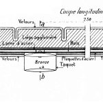
- Figure 9: Hocquart escalator, handrail details, Gare d’Orsay, 1908
-
- Figure 10: Hocquart escalator, transverse section, Gare d’Orsay, 1908
-
- Figure 11: Hocquart escalator, longitudinal section and plan, Gare d’Orsay, 1908
-
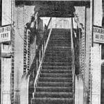
- Figure 12: Hocquart escalator, Gare d’Orsay, 1908
-
- Figure 13: Hocquart escalator, upper landing with motor, Gare d’Orsay, 1908

Get more of Elevator World. Sign up for our free e-newsletter.