The Other Otis Legend
Oct 1, 2025

A speculation
by Oskar Rosin
In the construction of the pyramids, Roman theaters and Greek monasteries, hoisting equipment played a “supporting” role everywhere. Such systems were also used early on in mining and soon bridged considerable hoisting heights.
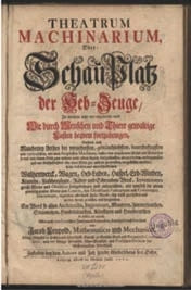
However, the transportation of people was limited to a few individual cases. The first reports on this can be found in Jacob Leupold’s book Theatrum Machinarium, published in 1725. Chapter XII “Machines to raise or lower themselves” reports on the “Fahr-Stuhl” (“Elevator”) of Mr. D. Weigel (1667) in Jena, Germany, which caused a “great sensation,” but of which there are unfortunately no records or descriptions. It also mentions a “chair” by the master model maker Gärthner from Dresden, Germany, which he used “daily with great comfort” both for going down and going up. Also of interest in this book are the description and illustration of a:
“Fahr-Stuhls, worauf ein Mensch über und unter sich, und also aus einem Zimmer oder Stockwerck in das andere gelangen kann.” (“A moving chair on which a person can move above and below themself, and thus from one room or floor to another.”)
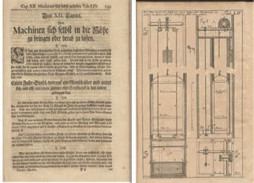
However, it is not known whether this rather “modern” looking construction was actually realized.
There are other reports of the French Emperor Louis XV commissioning a counterbalanced transportation system for his private rooms in Versailles in 1743. The Austrian Empress Maria Theresia also used a passenger transportation system in the west wing of Schönbrunn in 1772, and in 1793 Catherine the Great commissioned the Russian inventor Kulibin to develop an armchair with which she could move between the floors of the Winter Palace in St. Petersburg. Kulibin chose a spindle drive to raise and lower the chair, which was operated by a servant.
In English mines, accidents involving the transportation of people in shafts often resulted in fatalities due to rope or chain breakage. Statistics published in The Mining Journal in 1848 show 415 deaths in the mines of Wales, Lancashire, Staffordshire, Cornwall, Derbyshire, Durham, Northumberland, Shropshire and Cumberland, 89 of which were caused by the failure of ropes and chains alone.[1] As Dr. Lee Gray reported in ELEVATOR WORLD, George Prior developed a “Machine to Prevent Accidents in Descending Mines” back in 1807, a safety gear similar to the one Elisha Graves Otis demonstrated at the 1854 World’s Fair in New York’s Crystal Palace.[2]
And in Emil Maximilian Dingler’s Polytechnisches Journal, a patent by Edward N. Fourdrinier on “improved apparatus for lifting and lowering loads in mines etc.” dated February 1, 1847, is reported.[3]
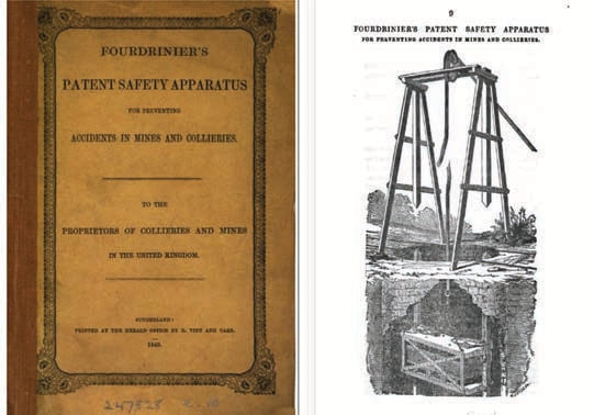
The English newspaper Staffordshire Advertiser published articles in 1848 about Fourdrinier’s invention of an ingenious device with the headline: FOURDRINIER’S PATENT SAFETY APPARATUS FOR PREVENTING ACCIDENTS IN MINES AND OTHER PLACES WHEN THE ROPE OR CHAIN BREAKS.[4] In a 1849 brochure of Fourdrinier’s patent addressed to owners of mines and collieries, there is also an article that describes how, shortly after the patent was granted, Fourdrinier stood at the top of a shaft on a loaded basket and ordered the rope to be cut (as Elisha G. Otis also demonstrated at the New York World’s Fair in 1854).[5] The basket was held on the rails by the “Safety Apparatus” instead of falling to the bottom of the pit.
In addition to the letter to the editor of the Mining Journal, correspondence with the manager of Wearmouth Colliery confirming the successful use of the invention, a letter from a colliery inspector to the editor of the Gateshead Observer about successful trapping trials with Fourdrinier’s “Safety Apparatus” and certificates of participation by mine owners, supervisors and engineers in trials demonstrating the effectiveness of the safety gear, there is also an illustration showing a cage fixed to the rails in the mine shaft by the safety gear with the rope cut.
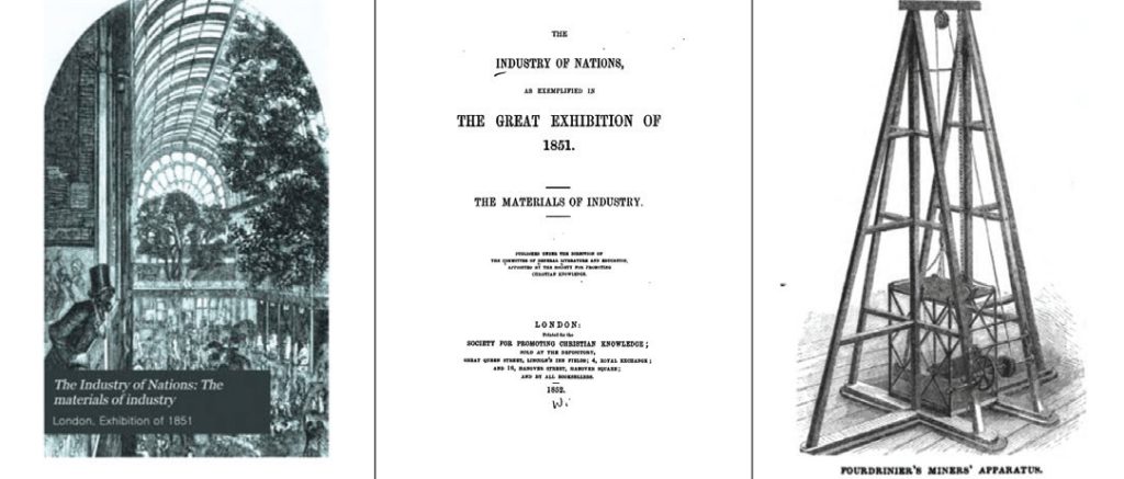
The catalog of the “Great Exhibition” — the London Industrial Exhibition of 1851, which took place from May 1 to October 11 in Hyde Park in London as the first world exhibition in the Crystal Palace — also reports on Fourdrinier’s safety apparatus and the successful attempts to hold the loaded basket on the rails when the rope was cut to prevent it from falling.
Yet, there is also a report of an accident that took place in 1852 in the Loscoe colliery near Belper, England. Two miners fell into the shaft together with the pit cage. Although Fourdrinier’s patented safety device was used, it could not prevent the pit cage from falling. However, it was not possible to determine whether the failure was due to a fault in the device or the flexibility of the timbers.
In December 1850, two articles appeared in the Practical Mechanic’s Journal on safety gears on pit cages in mining, which were also reproduced in Dingler’s Polytechnisches Journal with illustrations.[6] The first is entitled “Safety Platform and Self-Releasing Hook for Mine Hoisting Chutes,” and deals with a development by engineers White and Grant. If a rope or a connecting link breaks, an elastic spring presses toothed parts of roller surfaces against the wooden guide rails. This brings the platform to a standstill.
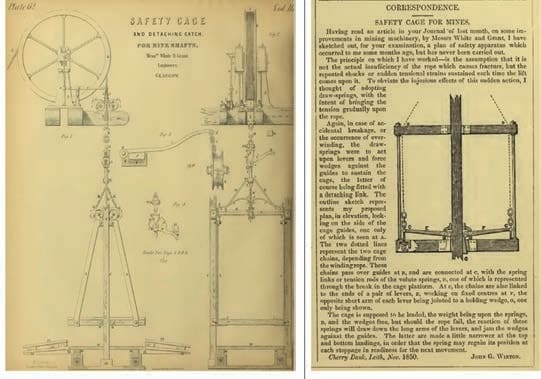
The second article reports on a “safety platform for mine shafts” by John Winton. Tension springs, which are intended to dampen excessive changes in tension in the suspension cables, act on levers in the event of a break in the suspension means, driving wedges between the guide rails and the platform so that the platform is fixed in place.
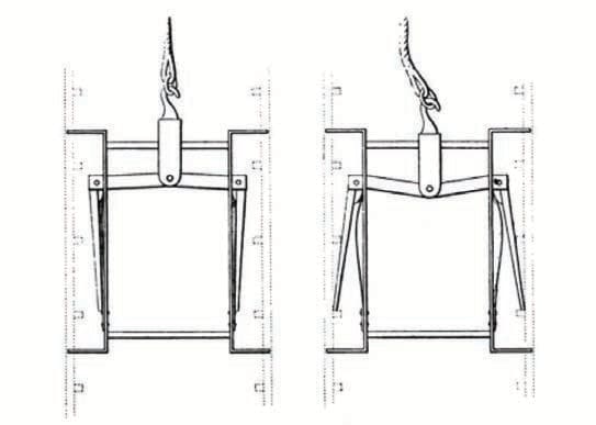
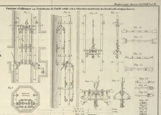
In the Bulletin de la Société d’Encouragement of 1854, one finds the “Description of a safety device or so-called fall brake to prevent accidents that can occur in shafts due to breakage of the hoisting rope” by Mr. Fontaine, machine foreman at the coal mines at Anzin in Northern France.[7] This article is also reproduced in Dingler’s Polytechnisches Journal with illustrations that show that “of the many drop brakes that have been invented over the years, Fontaine’s stands out for its practicality, which has been recognized both in France and in Belgium.”
This fall brake was already mentioned in a preliminary description in Volume I of the fifth series of the Annales des Mines in 1852.[8] The author was the Imperial Departmental Mining Engineer Comte from Anzin. This description also appeared as a translation in the Berg- und Hüttenmännische Zeitung in 1852.[9] Since then, this fall brake has been modified and improved and is described and illustrated in the Annales des Travaux publics de Belgique:
“In 1851, several tests were carried out with the apparatus at Anzin, which were repeated before its introduction in Belgian coal mining and described in the last-mentioned source, p. 199. On April 3, 1853, Fontaine’s falling brake was tested in the Alliance shaft of the ‘Nord du Bois de Boussu’ coal mines in the presence of Chief Mining Engineer Gonot from Mons, several other royal mining engineers and the inventor of the device. In the presence of the chief mining engineer Gonot of Mons, several other royal mining engineers, as well as the inventor, and the directors and officials of the mine, a test was carried out and a report was drawn up, from which the following is taken: A hoisting frame of three levels, which was equipped with a fall brake, was suspended at the end of a rope, the running meter of which weighed 2.5 kg. In each of the two lower tiers, a sheet metal wagon was placed, which weighed 130 kg and held 4 ½ hectoliters of coal.
“The hoisting frame prepared in this way was conveyed into the shaft at a speed of about 2.5 m/s; it was guided by two guide rods made of oak wood and attached to bolts at intervals of 2.5 m, the ends of which were embedded in platform holes. During the descent, the rope was cut at the shaft opening. The noise caused by the rope falling onto the top of the frame immediately indicated that it had been stopped and that the fall brake had therefore worked.
“It is clear from the above that Fontaine’s fall brake fulfills its purpose perfectly, i.e. it completely prevents the hoisting gear to which it is connected from entering the shaft as soon as the hoisting rope breaks.”[10]
In mining in Germany, the transportation of miners using hoists was prohibited until well into the 19th century. It was only with the invention of the art of transportation in 1833 by the senior miner Georg Ludwig Dörell in Clausthal, in which wooden rods equipped with steps moved up and down alternately in the shafts so that the miners could move vertically by changing from one rope to the other, that it was possible to penetrate ever-greater depths within the shafts. And with the development of the laid wire rope by Clausthaler Oberbergrat (a senior mining official associated with Clausthal, Germany) Julius Albert, the chains used until then, which were damaged by rolling up and down and sometimes broken with disastrous consequences, were replaced, so that modern mines of the late 19th century were able to set up passenger transportation by rope.
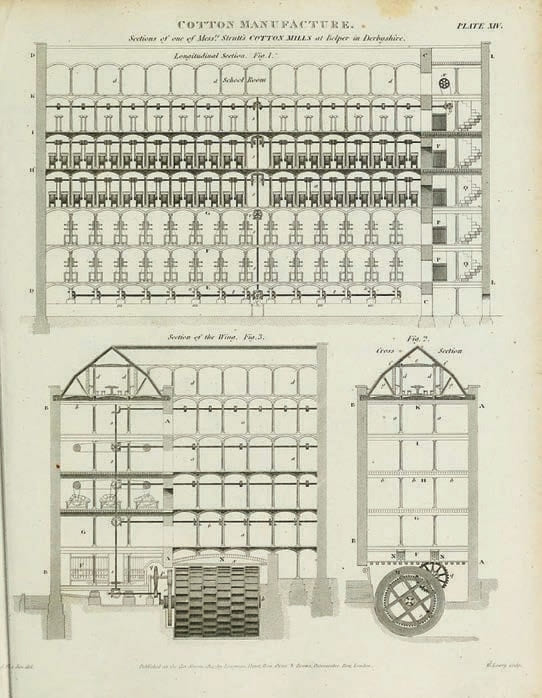
In contrast, vertical transportation (VT) of people in factories was promoted during the industrial revolution. The first description of such a system can be found in Abraham Rees’ Cyclopedia or Universal Dictionary of Arts, Sciences, and Literature, published in 1819, in which he describes the drive and control of a crane in the cotton mill operated by Henry Strutt in Belper, Derbyshire (central England), in 1803.[11] The crane was used to transport goods and workers up and down the factory building in a basket. In a more detailed description from a later volume, the basket is moved by a transmission driven by a mill wheel. According to Rees, this is “an extremely ingenious and useful machine, which is used by Mr. Strutts in all his cotton mills and is also used in many other manufactories.”
In the illustration of the spinning mill, the staircase “Q” connecting the floors is shown at the front of the building. Next to it is the shaft “P,” in which the basket and a counterweight move, whereby the counterweight balances the weight of the basket and half of the usual load that the crane is supposed to carry. The basket is steered by control cables operated by a boy who sits in a seat at the top of the cage. The cage itself has walls on three sides. The fourth side is open for access. The shaft has a closing gate on each floor to prevent people from falling into the shaft. These gates can only be opened when the basket stops at the corresponding floor because the latch of the gate is lifted by the basket when its floor is level with the gate.
A further description of this “crane,” now called the Teagle (Tackle?) or Hoist, is to be found in a book published in 1835 by Andrew Ure titled The Philosophy of Manufacturers, where some alterations have evidently been made from the original 1803 version.
The mechanism of the Teagle is understood by the following description and drawing, taken from one of the most improved forms by Frost of Derby, who, with the late William Strutt, Esq., received credit for inventing this very elegant automatic machine.
In this drawing of the Teagle, the boy’s control position at the top of the cage is no longer shown. It is now controlled by ropes running through the cage, which are operated by the respective user.
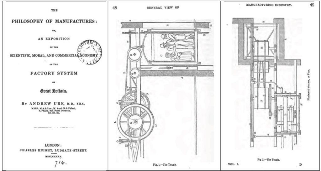
This report is also published in the Polytechnisches Journal in 1835 under the heading, “Ueber einen Apparat, dessen man sich in den größeren englischen Fabriken bedient, um die Arbeiter aus einem Stokwerke zum ande= ren emporzuschaffen, Mit Abbildungen auf Tab. II.” (“On an apparatus used in the larger English factories to transport workers from one floor to another. With illustrations in Table II.”)[12]
The Teagle had therefore already found its way into the VT industry in this or a similar form as a goods elevator and — according to Dr. Lee Gray — it can be assumed that similar freight elevators were already to be found in American factories in the early 1840s.[13] In 1856, the Parsons Paper Company spinning mill in Holyoke, Massachusetts, had a freight elevator similar to the Teagle in its general configuration. As these freight elevators were not only used for transporting goods in American factories, but were also frequently misused by workers, people were injured or killed in the numerous accidents caused by breakage of the load-bearing equipment.
This was the initial situation in the U.S. when Elisha Graves Otis (1811 – 1861) was commissioned in 1852 to install machines for the bedstead company Maize & Burns and to construct a goods elevator. He began to think about safety devices that would prevent the car or platform from falling if the load-bearing means (rope or chain) failed. The result was a device in the form of a strong steel spring to which the suspension rope was attached so that the spring was tensioned by the weight of the platform. If the cable breaks, the spring relaxes. The ends of the spring engage in toothed rails that are attached to the guides and hold the platform in place.
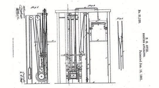
The platform with the safety device was exhibited and demonstrated in 1854 at the second world exhibition in New York’s Crystal Palace by cutting the suspension cable of the loaded platform. It is reported that Otis himself stood on the platform and—like Fourdrinier a few years earlier—gave the order to cut the suspension cable and then commented with the words “All safe, gentleman, all safe” that the platform was fixed in place after a few centimeters of free fall. Otis had thus created, as he put it in his patent specification, “a new and Improved Hoisting Apparatus,” i.e., he had added a safety device to goods elevators with the aim of stopping a hoisting device at any point – even if the suspension rope broke.
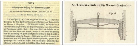
However, Otis’ demonstration did not cause the sensation that his sons later publicized. It was only reported in the U.S. in the New York Tribune and Scientific American. A further publication can be found in the U.K.’s Practical Mechanic’s Journal and in Dingler’s Polytechnisches Journal.[6,14] The latter article even points out that this “invention” is used for “securing elevators for moving goods upwards in warehouses” and that “similar devices have long been used in shafts.” Otis — as well as Fourdrinier — made the previously used lifting equipment safer with their inventions, but the invention of the elevator as we know it today and its use by everyone was not their ambition. Others had the vision of safely transporting people vertically in ever taller buildings: Peter Cooper (1791 – 1883) and Otis Tufts (1804 – 1869).
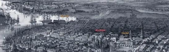
In the early 19th century, buildings in the metropolitan areas on the East Coast of the U.S. grew in height due to rising land prices. However, there were also limits to the growth in height. The condition of the users limited the height growth to five to six floors. And the elevators, which were used in factories and in some hotels to transport goods, were not considered safe enough to be used for passenger transportation due to numerous accidents — falls because of rope or chain breakage.
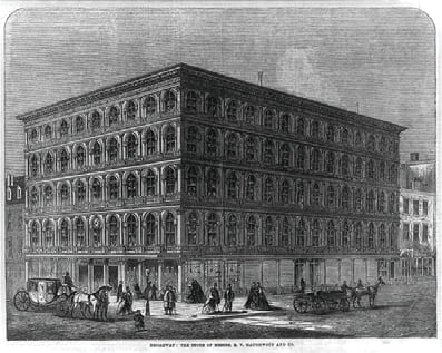
In 1857, Otis built an elevator in the E.V. Haughwout and Co. department store on Broadway in NYC, which was equipped with the safety system presented at the World’s Fair. However, the elevator, which was more of a “freight hoist” than an elevator intended for transporting people, was not appreciated by customers and was replaced after three years. It can therefore hardly be regarded as the first passenger elevator, as it is still portrayed in the literature today.
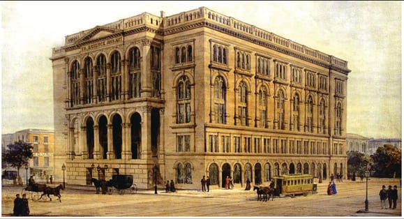
The inventor and industrialist Cooper opened a rolling mill in Trenton, New Jersey, in 1845 for the production of standardized steel beams for building construction. He believed the future of cities lay in the conquest of the vertical, that the development of fireproof high-rise buildings was urgently needed and that safe passenger VT would also be available in the foreseeable future. Therefore, when planning the Cooper Union Foundation Building in 1850 — in which educational opportunities were offered to people from all social classes and a large hall for cultural events resided — he also planned for an elevator shaft with access to all floors.
The building was one of the first in NY to be constructed with the standardized steel supports developed by Cooper and manufactured at his steel mill. Construction of the building began in 1853 was completed in 1859 and became one of the tallest buildings in Lower Manhattan when it opened.
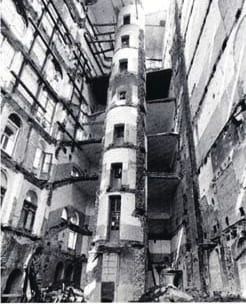
The free-standing elevator shaft erected inside the building was a sensation, particularly due to its round cross-section, as the usual freight elevators (freight hoists), which were already numerous in factories, had rectangular platforms and shaft cross-sections. Cooper opted for the round shape, as he reportedly believed this was the most efficient way of accommodating the most people in a shaft in terms of space and VT. However, the round cross-section was also the reason the first steam-powered elevator with a round cabin was not installed in this building until a few years later by Peter Cooper’s son Edward.
Around the same time the Cooper Union Foundation Building was being planned and built, another inventor had the vision of transporting people vertically as safely as the railroad could horizontally. Tufts — who built printing presses, steam engines and fire-fighting equipment, as well as invented the steam-powered pile driver, built the first double-hulled, iron steamship and the first all-iron ship in the U.S. based on the designs of John Ericsson — planned a “vertical railway” to reach the higher floors of buildings easily and effortlessly.
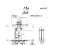
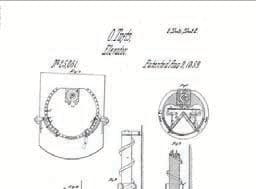
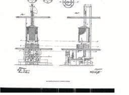
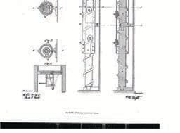
As can be seen from his patent specification dated August 9, 1859 (see Figure 6), his aim was to build an elevator for transporting people from the various floors of hotels, public buildings and even private residences that would be free from the dangers of suspension by chains, ropes or cords of any kind, as he felt he could not rely on their safety. He therefore chose the principle of a screw or a rotating helical column that extends from the bottom to the top of the building. The car is attached to a “nut” that runs along this screw. The screw is then turned by steam power or another type of driving force. To prevent people from falling into the shaft when the car is not at the respective landing, a lever system is provided with which the doors of the building’s galleries are opened and closed and automatically locked by the cams of the upward or downward traveling car.
As a further safety measure, car doors are provided to protect passengers from risk of entrapment between the car and the shaft wall. For this purpose, the car doors are opened and closed with the aid of a system of levers, springs and cams, which are fitted at each landing on the sides of the opening in the floor of the car or in the shaft. In addition, the car is fitted with a canopy or fixed cover to prevent objects falling from the upper floors onto the passengers. The necessary light or air openings are protected with grilles or nets so that passengers’ heads or arms do not protrude above the car and are thus protected from injury.
It was unusual that this “vertical railway” had a round elevator car, as the goods elevators installed in the factories usually had rectangular load-bearing devices. This leads to the assumption that either Tufts was aware of Cooper’s building project and the round elevator shaft, or that Cooper had intended his round shaft to accommodate Tufts’ elevator. It would certainly have been easier for Tufts to install the closing and locking devices for the shaft and car doors on his elevator on straight doors and not on curved ones. Unfortunately, no evidence for this speculation has yet been found in the literature of the time.
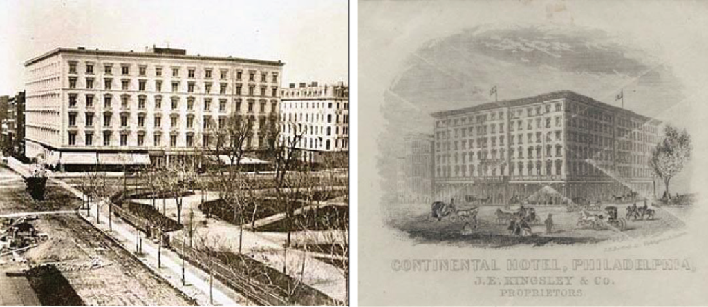
What is certain is that Tufts installed his “vertical railway” in two of the most important hotels of the time: the Fifth Avenue Hotel in NYC and the Continental Hotel in Philadelphia. The installation in the Fifth Avenue Hotel was put into operation in 1859, the same year that Cooper’s Foundation Building was opened. The Fifth Avenue Hotel was a luxury hotel (1859 – 1908) that offered guests the convenience of easy access to the upper floors with the Otis Tufts elevator. The system was safe but also extremely expensive. The other of the only two elevators of this type was built in the Continental Hotel, which was the most elaborate hotel of its time when it opened in 1860. The elevator in the Fifth Avenue Hotel ran smoothly for 15 years, but the brakes on the Continental Hotel elevator failed and the car slipped, causing one person to sustain injuries.

On January 23, 1860, a lengthy article appeared in the New York Times with the title: “Steam versus Stairs – The Movable Room in the Fifth-avenue Hotel – Value of the Principle for Private Residences, and for all ‘Elevators.’” In addition to describing the elevator — a square shaft with a side length of approximately 10 ft—it also expresses the hope that “this new and excellent device will be widely used in public, private and commercial buildings” and that it will save old and sick people the trouble of climbing stairs. Otis’ elevator in the E.V. Haughwout department store is not mentioned at all.
Even though Tufts was unable to achieve the desired breakthrough and success, as his elevator was too massive, too cost-intensive and not profitable with a larger number of floors, he and Cooper had nevertheless created the basis for transporting people in a “vertical railway,” which also became a safe means of VT through further inventions, such as the safety gear (1846), the traction sheave by the mine director Friedrich Köpe (1877), the electric drive by the company Siemens & Halske (1880), etc. These innovations made elevators a safe means of VT without which a skyscraper would be unthinkable.
References
[1] Edward N. Fourdrinier, Fourdrinier’s Patent Safety Apparatus for Preventing Accidents in Mines and Collieries. To the Proprietors of Collieries and Mines in the United Kingdom (1849).
[2] Dr. Lee Gray, “Elisha Otis at Crystal Palace, Part 2”, ELEVATOR WORLD (February 2022).
[3] Emil Maximilian Dingler, Polytechnisches Journal, Vol. 104, p. 458 (1847).
[4] Shaffordshire Advertiser, February 26 and March 4 (1848).
[5] Staffordshire Advertiser, June 23 (1849).
[6] Practical Mechanic’s Journal, December, p. 193 and p. 205 (1850).
[7] Bulletin de la Société d’Encouragement, May, p. 278 (1854).
[8] Annales des Mines, 5th Series, Volume I (1852).
[9] Berg-und Hüttenmännische Zeitung, No. 39. (1852).
[10] Annales des Travaux publics de Belgique, Vol. XII, p. 187 (1853-1854).
[11] Abraham Rees, The Cyclopedia or Universal Dictionary of Arts, Sciences, and Literature, Vol. 21, p. 760 (1819).
[12] D. Johann Gottfried Dingler, Polytechnisches Journal, Vol. 58, Issue 2, „Ueber einen Apparat, dessen man sich in den größeren englischen Fabriken bedient, um die Arbeiter aus einem Stokwerke zum ande= ren emporzuschaffen, Mit Abbildungen auf Tab. II.“ (1835).
[13] Lee E. Gray, From Ascending Rooms to Express Elevators: A History of the Passenger Elevator in the 19th Century (2002).
[14] D. Johann Gottfried Dingler, Polytechnisches Journal, Volume 133, No. XCIX, p. 415 “Security elevator for goods magazines” (1854).

Get more of Elevator World. Sign up for our free e-newsletter.
![]()


![]()