Traditional Lift Products
Jul 1, 2014

Hydraulic company has provided the U.K. with lifts since 1999.
Traditional Lift Products Ltd., located in the historic city of Liverpool, U.K., was formed in 1999 by a group of three entrepreneurs following the closure of the Otis factory in Liverpool. The Otis factory had operated since 1956, producing various lift products over the years, including machines, controllers, high-rise lifts and escalators. During its final years, production had focused on highly bespoke lifts, which were supplied to the Far East, Middle East and European markets.
At first, Traditional helped finish the longer-term Otis projects. However, being independent, it quickly branched out by developing other customers, including Schindler, KONE, Fujitec, Mitsubishi Electric and ThyssenKrupp, plus many independent lift companies. Half of the bespoke lifts it had been working on with Otis had been hydraulic, making its employees familiar with such OEMs as GMV, Leistritz and Bucher, which had been used with good results. Since it needed extra workers, Traditional secured the skills of Peter Pike and Mike Bukata, who, together, brought more than 70 years of design experience with hydraulic lifts to the company.
M&S Store, London
One of the first projects we worked on as a new company was two hydraulic lorry lifts for the M&S store on Fenchurch Street in London. The lifts had an internal size of 12.5 m deep, 4 m wide and 4.5 m high, suitable to move articulated lorries from the street level down to the second basement level 12.5 m below. With a combined car mass and duty load of 70,000 kg, a bespoke solution was needed, and after much thought and discussion with the client, a four-ram arrangement was selected. The system uses direct-acting rams located under the lift car, which required 14-m-deep boreholes with diameters of 700 mm. Four UC1200 Bucher power units were used to power the rams, which required more than 170 kW when the lifts were traveling in the up direction at 0.15 mps under full load. The four pumps used were joined via a manifold, which distributed through a pipe to each ram. To avoid the issue of one tank filling more than the other, large-diameter balance pipes were used between the tanks, allowing the oil to siphon between them naturally.
The advantage of using the four-ram arrangement was that the mass of the lorry was supported by four stable points, which minimized the tipping moment (and hence, the guide-rail forces) should the lorry enter the lift over to one side. One of the greatest concerns was how the flow rate of oil to each ram could be controlled to ensure each ram traveled at a consistent speed. A system using a central control valve connected to the head of each ram was used to balance the flow rates to each ram. This was effective, preventing the rams from getting out of synchronization.
The pipework from the tanks to the rams required much thought and engineering. To avoid losses and cavitation, large-diameter steel pipes with welded joints were used with the minimum number of bends. Because it was decided not to use pawl devices to lock the lift car to the entrance during loading, the use of steel pipes was essential to minimize the amount of movement of the lift car in relation to the lobby as the vehicles entered the lifts. Re-leveling was also used to raise/lower the lift car as necessary when the lorry entered or exited the lift.
Despite only eight motor starts per hour, the lorry lifts generated large amounts of heat due to the large masses being moved. Thus, four oil air coolers were installed to exhaust the heat created from the 34 kW of power used per lift. The project was completed in 2002.
Oxford University Chemistry Building
Traditional also manufactures scenic glass lifts. One such installation was the lifts at the chemistry building (new in 2004) at the University of Oxford in Oxford, U.K. Two minimalistic lifts were required, with a maximum glazed area and minimum structure to serve the five floors within the building’s atrium. The busy building needed its lifts to handle 16 persons each at 1 mps. Though this speed is considered high for hydraulic lifts, the main issue was their travel distance of 21 m.
The ram was designed in accordance with EN 81-2 standards, which requires a minimum buckling safety factor of 3.5. This would be exceeded if the car weight were too high, but if the car weight were not sufficient, it would not have enough pressure to push the oil back into the tank. The calculations predicted a minimum car weight of 2400 kg and maximum car weight of 2500 kg. Also, the architect’s requirement of maximum glass required the guides to be very close to the front, making it heavily cantilevered. To balance the lift car, further weight had to be added to the front. Careful preliminary analysis, then weighing and balancing the assembled lift car offsite ensured the car did not need to lose any weight.
The ram, more than 22 m long, needed to be split into two sections. The team had to make sure it plumbed the ram accurately to prevent poor ride quality and premature wearing of the sliders that guide it. This was accurately achieved by fully extending the ram and using plumb lines at 90°.
The client also wanted to get the benefit from all the energy the lift created. Oil-to-water heat exchangers (thermostatically controlled in conjunction with the oil pump) were used for this, for which the builder provided the cold-water supply.
St Pancras Station HS1 Project and Thameslink Box
Traditional’s largest single order for hydraulic lifts was secured for the High Speed 1 (HS1) project at St Pancras, Stratford and Ebbsfleet stations. A total of 27 lifts were required in 2007 and 2008, including vehicle, goods, passenger and scenic designs. These were largely of the borehole type, with both two and four rails. Two-to-one solutions were used at the Ebbsfleet and Stratford stations, however, and a couple others had cantilever solutions.
All the lifts were supplied in accordance with EN 81-2, while Traditional strived to adhere to consultant specifications. The first lift on site was a scenic lift in a highly detailed glass structure to be supplied in accordance with CTRL specifications, but as the lowest level served the London Underground, it also needed to focus on that system’s specifications. With reliability and longevity in mind, controllers were sourced from Dewhurst, hydraulics from Bucher, passenger lift door systems from Sematic and shutter gates from Bolton gates. The other significant requirement was to achieve high levels of safety for both passengers and maintenance engineers. Due to the location of the lifts, the machine rooms were below platform levels and accessed via a maintenance hatch and hinged ladder. This led to some water-table issues. A couple of the machine rooms flooded before handover, but fortunately, there was time for the builder to drain the water and seal the leaks, and for new control equipment to be installed.
Later, lifts were installed at the Thameslink area to the specifications of both CTRL and Network Rail. Network Rail is the company that manages the majority of track and station infrastructure in the U.K. Network Rail has well-defined specifications for hydraulic lifts and is particular about the technology and suppliers to be used. It has a preference for Bucher equipment and demands the highest technology available, including variable-voltage, variable-frequency systems (to control the flow rate to the rams) and accumulator technology.
The best way to describe an accumulator system is a hydraulic “counterweight.” It is more expensive than other alternatives but has major advantages in terms of improved efficiency and reduced power consumption/supply current. As the lift descends, compressed air (created by the oil above the air) is stored in multiple tanks. As the lift ascends, the energy is released back into the system, forcing oil into the ram. Bucher’s figures show this can be more energy efficient than a conventional traction lift.
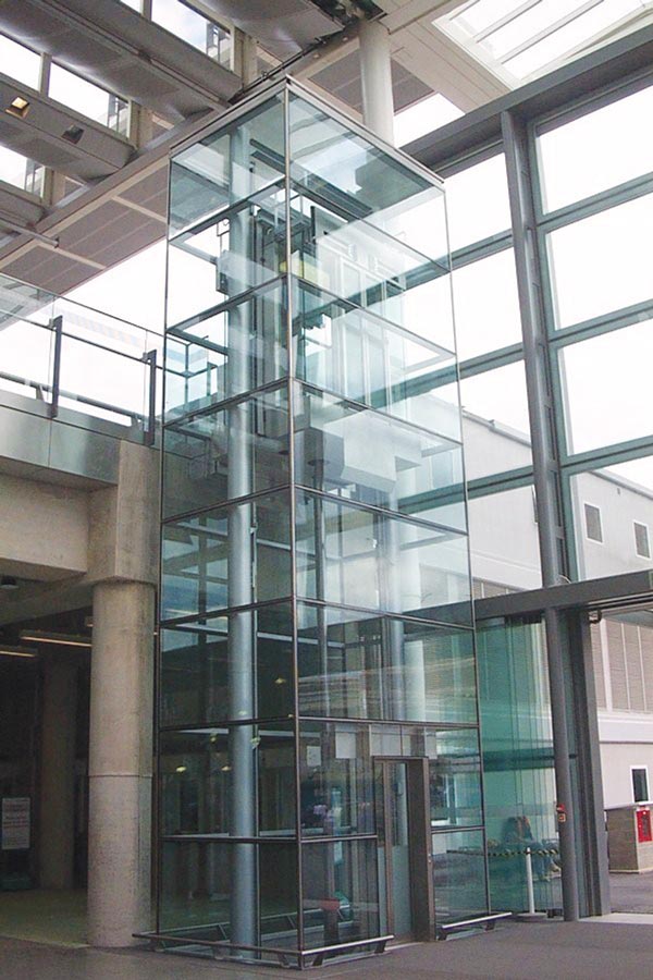
A scenic lift at a rail station conforming to CTRL specifications. 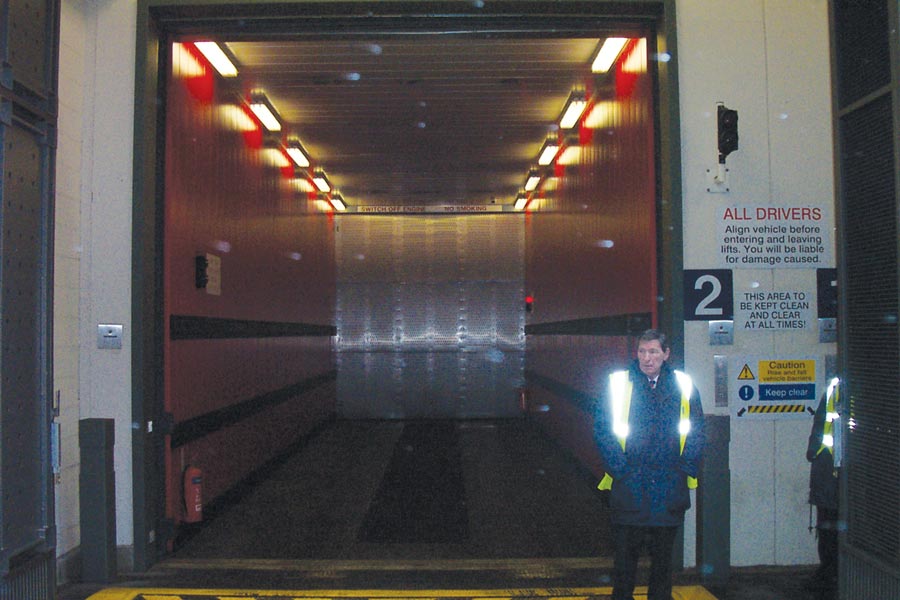
A 40-T-capacity lorry lift at the M&S store 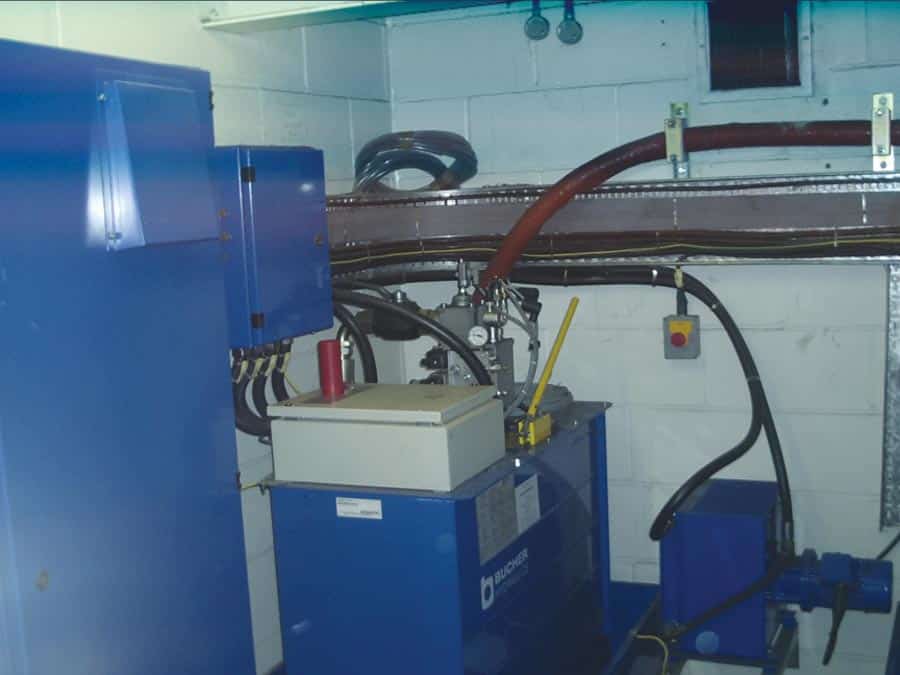
A machine room in a rail-station installation conforming to CTRL specifications
Get more of Elevator World. Sign up for our free e-newsletter.