Using Multiphase Drives as the Elevator Propulsion System
Nov 1, 2018

Separately exploring use of a six-phase inductive motor and six-phase matrix converter in effort to boost reliability and efficiency of elevator drives
by Davoud Karbalaei, Amir Bahram Daraei and Hossein Bakhtiari
This article investigates the performance of multiphase motors for use as drives for traction elevators and shows their advantages when compared against three-phase motors. Various converters can be used to control motors, and the one used here is called a “matrix converter.” This converter has many advantages, due to the elimination of DC bus capacitors, one of which is the diminution of the control-drive dimensions. Therefore, the use of a matrix converter enables motor/drive integration, which will reduce the size of the control system, especially for projects without a motor room.
Introduction
In industrial applications, and the direct-on- line (DOL) setup procedure of the motor without a drive, three phase is quite logical, because the electricity network is based on it, and the use of motors with more than three phases usually does not make sense. Also, due to the advantages of three-phase motors in comparison to single- phase motors, output power increases dramatically only by increasing the phase (two single-phase wires in a single-phase system and three wires in a three-phase system). In other words, with a 50% increase in copper, output power will increase by 200%. Simple control of the motor is possible when motor control (MC) is done using the drive with the desired number of output phases. Therefore, in this situation, the use of motors/drives with more than three phases can be investigated. This article addresses this issue, considering the standard requirements for the use of drives in traction elevators.
On the other hand, a matrix converter is considered one of the newest types of converters, considering the advantages it has for use in controlling elevator motors. Its smaller dimensions, power factor and possibility of returning the energy to the grid (instead of its loss in the braking resistor) are the most important reasons for the attractiveness of this type of converter. In the following, a six-phase inductive motor and six-phase matrix converter will be explored separately. Finally, the advantages and disadvantages of using these two in an integrated package will be described.
Six-Phase Induction Motor
Induction machines have been used for more than 100 years due to their advantages like structural simplicity, high power, good reliability, low cost, reasonable volume and weight, and good efficiency. Now, more than 90% of rotational industrial activities are done by three-phase induction motors.[1]
Multiphase motors with phase number n (n> 3) make up a new generation of motors that are often used today in high-power applications with high reliability. The six-phase motor has six separate coils, which can be equated as two series of three-phase coils. Figure 1 shows a schematic of this type of motor, in which two series of winding wires with an angle of 30° (each of which has 3 phases), the angles between the phases of each group is 120°.
In this scheme, all coils are common at one point, and so is the design of the connection of the star. To analyze and control this motor, it is necessary to analyze its electrical circuit. To control the vector of this kind of motor, the equations are written and analyzed in two vertical axes, q and d.[3] The equivalent circuit of the motor phases on the two axes are shown in Figure 2. Since six independent currents flow through six phases of an induction motor, the six-phase machine is essentially a six-dimensional system. The flow variables over time can be represented by a vector in a six-dimensional space (Figure 2).
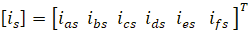
Stator currents with a six-dimensional vector are:
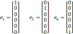
This vector has six base vectors:
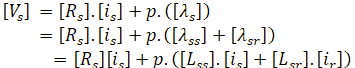
According to these definitions, a six-dimensional space d-q-z1-z2-o1-o2 is defined,[4] and the stator voltage equation is:
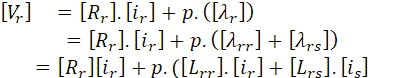
The rotor voltage equations are:
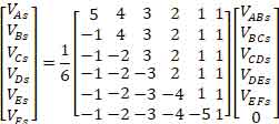
In the transformation of the vector of the output voltages of the inverter into the reference frame d-q-z1-z2-o1-o2, with the connection of the stator windings to the inverter output and without connecting the neutral points, only the line voltages of the machine are directly known. In other words, the conversion matrix (Equation 5) converts the machine phase variables to the new reference frame d-q-z1-z2-o1-o2. Therefore, conversion from line voltage to phase voltage is essential.
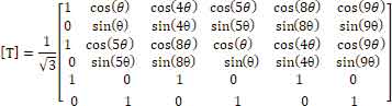
If the neutral points of two sets of winding wires of the three phases of the motor are connected together, after converting the line to phase voltages, the conversion of the line voltages to the phase voltages is derived by the inverse of the transformation matrix:[4]
The above are fundamental relationships in analysis of the six-phase motor and can be used to analyze the motor’s steady state. The most important advantages of a six-phase engine over a three-phase engine are:[5-9]
- Enhancing reliability Reduced DC bus harmonics
- Reducing rotor harmonic current and power losses
- Reducing torque fluctuations
- Better power distribution in motor phases
- Improving the power profile
- Increasing efficiency
Matrix Converter
Two-stage electrical inverters are usually used to control the elevator motor. As shown in Figure 3, the structure of these converters consists of three parts: rectifiers, DC bus and inverters. The rectifier part consists of only six diodes and acts as an uncontrolled rectifier. So, there is no control over the amount of power that enters the drive. The DC bus section contains two or more capacitors. The lifespan of the capacitors and their relatively large dimensions creates some limitations. Also, injection of additional energy into the braking resistor is done by the relevant elements, often insulated-gate bipolar transistors (IGBTs). The inverter section is responsible for generating different voltage waves at different frequencies, according to the motor state and optimum condition.
A matrix converter is a power converter with compulsory commutation. This converter, which, in fact, is a matrix of two-way switches, establishes a direct relationship between input and output. The matrix converter needs less space due to the direct relationship it makes between inputs and outputs and has no need for bulky energy storage elements such as DC bus capacitors compared to other conventional power converters. Also, the absence of a capacitor in the converter structure increases its reliability. The matrix converter is another type of converter that does not have a DC bus and capacitors, and two rectifier and inverter sections are combined. [10]
Gyugyi-Pelly first presented the main structure of the matrix converter in 1976.[11] However, the real development of the matrix converter with the work of Venturini and Alesina began in 1980[12]. They introduced the converter circuit as a matrix of bidirectional power switches and introduced the name. One of their most important goals was the development of a robust mathematical analysis to describe the low-frequency behavior of the transducer, referred to as “Low Frequency Modulation Matrix”. In this modulation, also known as the “Direct Transfer Function,” the output voltage is obtained by multiplying the modulation matrix at the input voltage.
A different control method based on the theory of “Fictitious DC-link” was introduced by Rodriguez in 1983.[13] In this way, switches are placed such that each line between positive and negative inputs is switched by the pulse-width modulation (PWM) solution, and the standard voltage source is used in the inverter. This is also known as the “indirect transmission function.” In 1985 and 1986, Ziogas published two papers describing the term “Fictitious DC-link” and providing a solid mathematical expansion.[13] In 1983, Brown and, in 1989, Costner and Rodriguez introduced the use of vector space in matrix converter analysis and control. Also in 1989, Haber introduced his first paper on “Green Space Management Systems (SPVM)” on matrix converter modulation.[14]
Modulation methods based on Ventorini theory are known as direct methods, while methods based on “Fictitious DC-link” are known as indirect methods. Kastner and Rodriguez, in 1985, as well as Schauder and Neft, in 1992, carried out practical experiments that proved that a single nine-key matrix converter
could efficiently be used to control the vector of a three-phase induction motor with high-quality outgoing and inlet flow.[15]
It is important to note that, in this case, the rectifier unit is fully controlled, and it is possible to return energy to the network by use of two-way keys. Combining the two parts of the rectification and inverter, and controlling it, makes the power factor one. Figure 4 shows a simplified schematic of a three-phase matrix converter, which consists of nine bidirectional switches. The matrix converter is connected to terminals a, b and c via the three-phase power grid and connected to the motor through the terminals A, B and C after making the necessary transformations. Each input phase can be connected at any time to each of the phases using the switches (Figure 4).
To analyze these types of converters, it’s better to simulate with conventional converters, then analyze them. The equivalent model is shown in Figure 5. The duty of a six-phase matrix converter in this paper is the transformation of the three-phase voltage to feed a six-phase motor. That means converting three-phase input to six-phase output. So, in this case, instead of nine bidirectional switches, 18 of these switches are needed. Figure 6 shows a simple design of such a model. As shown, each of the switches will be responsible for connecting each of the three input phases to each of the six output phases. The bidirectional switches themselves can have different structures. Two of the structures of these keys are shown in Figure 6.
In a six-phase matrix converter, a total of 18 matrix converter keys produce 729 different switching modes, of which 64 are allowed. The matrix converter voltages are in accordance with its 64 switching modes. Figures 7-9 show vectors transmitted to three d-q, O1-O2, Z1-Z2 screens.[16] It should be noted that the vectors placed on the O1-O2 plate are placed on a straight line. So, in fact, the system will be reduced to a five-dimensional system. When the number is converted to a binary six-digit number, the numbers on each vector determine the switching state.
A model developed for a six-phase machine states that only d-q voltages and currents are related to the conversion of electromechanical energy. Therefore, the purpose of controlling the space vector PWM (SVPWM) method is to extract the vector of d-q voltages so the torque is supplied. The mean of voltage-time in Z1-Z2 and O1-O2 plates should also be zero during the sampling period. The vector PWM strategy is performed with relation to:
where ![]() is the kth image of the voltage vector on the x axis, and Tk is the time of applying that vector over time Ts. Values
is the kth image of the voltage vector on the x axis, and Tk is the time of applying that vector over time Ts. Values ![]() and
and ![]() reference voltages are in the d-q page. During each sampling period Ts, a set of five voltage vectors must be selected in such a way that each Tk has a positive and unique value. There are several ways to select such a set. Equation 7 is used to analyze and apply the SVPWM method to a six-phase matrix converter.
reference voltages are in the d-q page. During each sampling period Ts, a set of five voltage vectors must be selected in such a way that each Tk has a positive and unique value. There are several ways to select such a set. Equation 7 is used to analyze and apply the SVPWM method to a six-phase matrix converter.
According to research,[11] & 13-15] the most important advantages of a matrix converter over two-stage common converters are:
- Sine wave inputs and outputs
- No need for reactive bulky elements
- The possibility of a unity displacement coefficient for each load type
- Performance for four areas
- Simple and compact design
- The ability to regenerate energy
- Rapid response
- Higher controllability
- Independence of the number of phases, waveform and frequency in both input and output
- Removing the capacitor and, thus, the ability to operate at higher temperatures
- No need for maintenance and repair
Six-Phase Control System
By combining a three-phase matrix converter with six phases and using a six-phase motor, all the benefits of using each is achieved. Considering that the use of a speed control drive is required in the elevator control systems, there is, therefore, no specific limitation in this regard. One of the most valuable features of this project is to increase the reliability and control of the propulsion system.
In conventional three-phase systems, if an IGBT or motor phase burns or disconnects, it’s impossible to control the motor. If the six-phase systems cut one of the phases, the system can still operate in five phases (with reduced torque, of course). Since an elevator usually works below nominal capacity, it is possible to use the system. In the event of an error and with a fault or fault detection, the control algorithm can control the motor with a five-phase-modified algorithm. It should be noted that there are various algorithms and methods for controlling such a system and with the occurrence of a given error. In one of these designs, by adding a bidirectional switch to the converter, output torque can be increased. The system may suffer from small torque fluctuations but can still perform reliably.[16-20]
On the other hand, knowing that the motor acts as a generator, its energy is transmitted to the drive in about half the movements. The energy returned to the drive is displayed as an increase in the DC bus voltage level, and, if the level of this voltage exceeds a certain limit, it will cause damage to the drive. To prevent this, drives should be equipped with a chopper circuit and a brake resistor to transfer and dissipate excess energy. But, using the converters with controllable rectifying parts, the energy from the engine can be returned to the power grid. The matrix converter also enables this, due to its structure and direct connection between the input and output phases, and the use of two-way keys. This is especially true for high-speed and high-rise elevators.
The removal of the DC bus capacitors can be examined in two respects: to increase the life of the drive and reduce its dimensions. Reducing dimensions, especially in elevators without machine rooms, is a decisive factor. On the other hand, with an increasing number of phases of the motor, the current flow rate of each phase in a six-phase engine is reduced to that of a three-phase motor with the same power. Reducing motor flow in this way reduces the power and, therefore, dimensions of the breakers and contactors, and the cross-section of the cables and terminals. In addition, a six-phase motor has smaller dimensions than a three-phase motor with identical power. As with the increase in the number of motor phases, both motors have smaller torque fluctuations than a single-phase motor.
The reduction of torque fluctuations and, consequently, the improvement of the quality of the lift curve can be economically justified for consumers on the basis of ride quality. Another advantage of this system is the increase in the power factor of the entire drive system compared to a conventional drive. By performing precise calculations and advanced control algorithms, a unity power factor can be obtained. Also, reducing the amplitude of the flow in the motor windings and drive path to the motor reduces the amplitude of the harmonics produced and has fewer damaging effects on weak signal-carrier wires.
Despite all the advantages mentioned, there are limitations in using this design. The first limitation is the cost of this control system. Given that the IGBT modules for mass-produced drives are produced by various manufacturers, the cost of the drives used by these IGBTs is low. While relatively new, matrix converters have a widespread lack of manufacturers, making them priced higher than conventional IGBTs. Also, few manufacturers have been introduced for six-phase motors, and the designs of these motors are bespoke, which also increases their cost. Due to the double- sidedness of the matrix converter, keys and the injection of energy into the power grid, filter use in the drive input is mandatory.
Proposed Design
According to the materials stated and the increasing need for increased quality, failure reduction, diminution of dimensions and increased reliability of control systems, this article proposes a design that is hoped to be welcomed by manufacturers and designers of control systems and electric motors. The plan includes an integrated motor/drive system. The control system of the motor/drive can be placed on the motor body due to the removal of the capacitor from the electronic converter system, and the reduction of the cross-sectional area, flow of motor wires and dimensions of the electric motor. This will reduce the power and signal paths (such as for an encoder) and create less electromagnetic disturbance in the surrounding environment. It also reduces the effectiveness of signal-carrying wires from noise and disturbances in the surrounding environment.
Connections from the elevator control system to the integrated motor/drive assembly include three power-supply motor drives and a communication control signal, such as the CANopen protocol. Many commands and feedbacks can be exchanged in the context of this serial communication and certainly will not require significant wiring. There is a need for separate wiring to control the mechanical brake of the motor and other important items, but, in general, the wiring from the control panel and the elevator controller to the motor/drive assembly is greatly reduced (Figure 10). Also, increasing application of the safe-torque-off (STO) function leads to removal of the motor contactors and reduces the wiring and cost of the product. It also reduces the dimensions of the motor/drive assembly. All of this leads to a significant reduction in the elevator control system and opens the way for projects that face space constraints, especially those without a machine room.
Conclusion
The use of six-phase control systems has many advantages over that of conventional three-phase systems, and investigations in relation to the performance and reliability of such systems have been done for several years. The six-phase control system also uses a newer matrix converter. By installing an MC system that can be used to remove drive capacitors and reduce the power of its key components, as well as attention to technologies such as the STO function and reliable communication protocols such as CANopen Lift, designers are provided with unique features for lift systems.
Reducing the dimensions of the drive and motor due to reduced nominal current and the cross-section of its coils, reducing the dimensions of the drive, removing the brake resistor (which saves energy consumption and creates favorable environmental effects), less power and signal wiring and, most importantly, increased reliability of the control system (which, even by cutting off one of the motor phases, can work properly), are the main features of the proposed design. Also, increasing the quality of the lift curve is due to the reduction of torque fluctuations due to the increase in the number of phases of the engine, as well as the reduction of disturbing harmonics. Increasing the power factor and reducing energy consumption, in general, are among the project’s other strengths. However, restrictions such as rising prices due to equipment limitation and a small number of companies that can implement such a plan will result in a higher cost than the usual plans at the start of the work. This proposal applies to gearboxes and compressors.
-
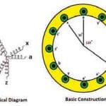
- Figure 1: Basic construction of a six-phase induction motor
-
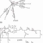
- Figure 2: d-q model of a six-phase machine
-
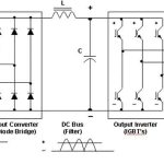
- Figure 3: Conventional inverter
-
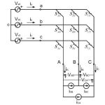
- Figure 4: Simple MC structure
-
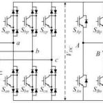
- Figure 5: A two-stage equivalent for three-phase MC
-
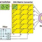
- Figure 6: Three-phase to six-phase MC
-
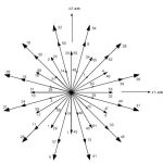
- Figure 7: Vectors in the Z1-Z2 screen
-
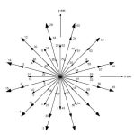
- Figure 8: Vectors in the d-q screen
-
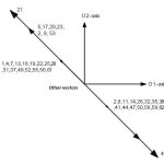
- Figure 9: Vectors in the O1-O2 screen
-
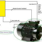
- Figure 10: Simplified scheme for proposed design
References
[1] Emil Levi. “Recent Developments in High Performance Variable-Speed Multiphase Induction Motor Drives,” Sixth International Symposium Nikola Tesla, Belgrade, Serbia. October 18-20, 2006.
[2] E.A. Klingshirn. “High phase order induction motors part-1, Description and theoretical consideration,” IEEE Trans. PAS. Vol. 102, No. 1, January 1983, p. 47-54.
[3] T.A. Lipo. “A D-Q model for six phase induction machines,” International Conf., Proceedings, Electrical Machines, Athens, Greece, 1980, p.
860-867.
[4] Y. Zhao and T.A. Lipo. “Space-vector PWM control of dual three phase induction machine using vector space decomposition,” IEEE Trans. on Ind. Appin., Vol. 31, No.5, September/October 1995, p. 1100-1109.
[5] M. Lazzari and P. Ferraris. “Phase number and their related effects on the characteristics of inverter-fed induction motor drives,” Conf., Proceedings, IEEE – IAS’83 Mexico City, October 1983, p. 494-502.
[6] R. Bojai, M. Chiado Caponet, G. Grieco, M. Lazzari, F. Profitmo and A. Tenconi. “Computation and measurements of DC link current in
Six-Phase voltage source PWM inverters for ac motor drives,” Conf. Rec. Pcc’02, Osaka, Japan, April 2002, p. 953-958.
[7] R.O.C. Lyra and T.A. Lipo. “Torque density improvement in a six-phase induction motor with third harmonic current injection,” IEEE Trans. on Ind. Appin. Vol. 38, No. 5, Appl. 2002, p. 1351–1360.
[8] R. Bojoi, F. Farina, A. Tenconi, F. Profumo and E. Levi. “Stationary frame digital current regulation for dual-three phase induction motor drives,” Proceedings of IEEE Power Electronics Specialists Conference, Aachen, Germany, 2004, p. 2121–2127.
[9] S. Smith. “Developments in power electronics, machines and drives,” IEE power Eng. Journal, No. 1, 2002, p. 13-17.
[10] Marco Matteini. ”Control technique for matrix converter adjustable speed drive,” PhD Thesis in Electrical Engineering, University of Bologna, 2001.
[11] L. Gyugyi and B.R. Pelly. “Static Power Frequency Changers. Theory, performance and applications.” John Wiley & Sons, 1976.
[12] M. Venturini. “A new sine wave in sine wave out, conversion technique which eliminates reactive elements,” Proc. POWERCON 7, 1980.
[13] P.D. Ziogas, S.I. Khan and M. H. Rashid. “Analysis and design of forced commutated cycloconverter structures with improved transfer characteristics,” IEEE Trans. Ind. Electron., Vol. IE-33, No. 3, 1986.
[14] L. Huber, D. Borojevic and N. Burany. “Voltage space vector based PWM control of forced commutated cycloconvertors,” IEEE IECON, 1989.
[15] C.L. Neft and C.D. Schauder. “Theory and design of a 30-HP Matrix Converter,” IEEE Trans. Ind. Applicat., Vol. 28, No. 3, 1992.
[16] B. Welchko, T.A. Lipo, T.M. Jahns and S.E. Schulz. “Fault tolerant three phase AC motor drive topologies: a comparison of features, cost, and limitations,” IEEE Trans. on Power Electronics, Vol. 19,No. 4, 2004.
[17] Y. Zhao and T.A. Lipo. “Modeling and control of a multi-phase induction machine with structural unbalance. Part I: Machine modeling and multidimensional current regulation,” IEEE Trans. Energy Conversion., Vol. 11, No. 3, 1996.
[18] S. Kwak and H.A. Toliyat, “An approach to fault-tolerant three-phase matrix converter drives,” IEEE Trans. on Energy Conversion, Vol. 22, No.4, 2007.
[19] Reza Kianinezhad, et. al. “A New DTC of Six Phase Induction Machines using Matrix Converter,” ACTEA, 2009.
[20] Karbalaei Davoud, Kiani Nezhad Reza. “Control of Six-Phase Matrix Converter Under Fault Conditions,” ICEE, 2011.
Get more of Elevator World. Sign up for our free e-newsletter.