Waveforms, a Little Trig and Elevator Design and Repair
Dec 5, 2022

Appreciating and understanding waveforms as applicable to elevator work

Value: 1 contact hour (0.1 CEU)
This article is approved for Continuing Education by NAEC for CET® and CAT®.
EW Continuing Education is currently approved in the following states: AL, AR CO, FL, GA, IL, IN, KY, MD, MO, MS, MT, NJ, OK, PA, UT, VA, VT, WA, WI and WV | Canadian Province of BC & ON. Please check for specific course verification of approval at Elevator Books.
Learning Objectives
After reading this article, you should have learned about:
- Waveforms
- Trigonometric function
- Three sides of a right triangle
- Using a thermal imager
- Why DC bus voltage is higher than the line voltage in a variable-frequency drive
Most elevator designers and technicians know exactly what a waveform is, but how many can define a trigonometric function? Actually, they are the same. Waveform is in the electronic engineer’s language, while the mathematician says trigonometric function. We won’t go too deeply into the trig part of it, but an overview will provide some context for appreciating and understanding waveforms as applicable to elevator work.
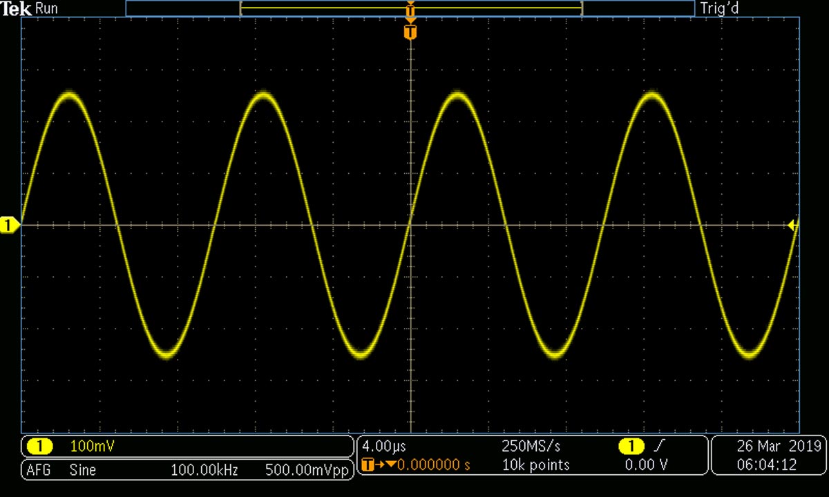
First, what is a waveform? Decidedly, it is not a realistic picture of an oscillating sound or electromagnetic energy wave, which instead consists of changes in density in air pressure for a sound wave, or changes of polar configuration in space for an electromagnetic wave. A waveform, in contrast, is a graph of instantaneous amplitude shown in Cartesian coordinates, so-called because its inventor, Rene Descartes, wrote under his Latin name, Cartesius. In the most familiar version, known as the time domain, the independent variable, time, is plotted against the horizontal X-axis in units of seconds or fractions thereof, while amplitude, the dependent variable, is plotted in volts against the vertical Y-axis. (The dependent variable always depends upon the independent variable. It would be a strange world if time depended upon amplitude.)
A less familiar but equally realistic version of the same sine waveform is shown in the frequency domain in a spectrum analyzer or oscilloscope with Fast Fourier Transform (FFT) capability.
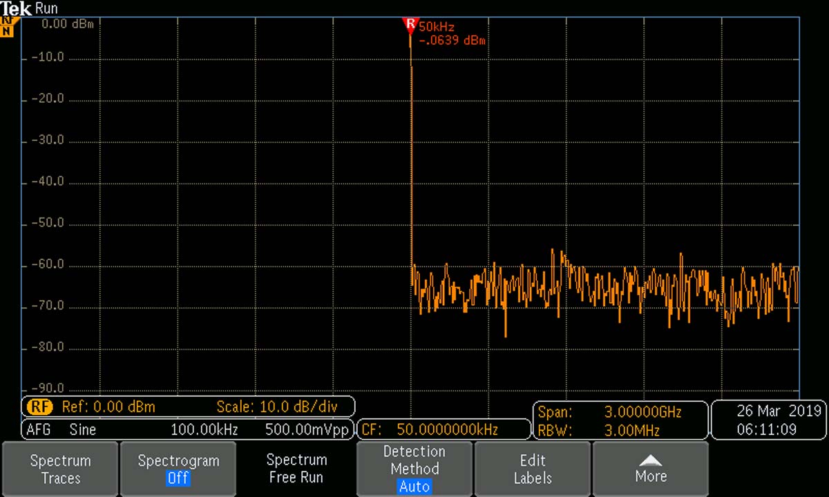
Here, frequency is the independent variable. It is plotted in Hertz (formerly cycles per second) against the horizontal X-axis. As in the time domain, amplitude is plotted against the vertical Y-axis, now in units of power or decibels rather than volts. The irregular line at the bottom, in which the rapid fluctuations are not visible in this still photograph, is the noise floor. Below it, no information can be accessed. This pure sine wave does not generate harmonics, except for the first harmonic, otherwise known as the fundamental.
These graphic representations are not what changes in air or spectral density looks like, but the images are very useful for elevator engineers in the course of their work, as we shall see.
First, some further background: What’s all this stuff about trigonometric functions? As stated above, this is in the language of the mathematician. Trigonometry is essentially the study of measurement of triangles, specifically right triangles. Old-time engineers would carry pocket-size books containing trigonometric ratios (sine, cosine, tangent, secant, cosecant, cotangent). They would look up the trigonometric ratio associated with any angle θ (Greek letter theta). From that, given any two sides, opposite or adjacent, they could calculate the length of the hypotenuse, or given the length of the hypotenuse and one side, they could calculate the other side. A slide rule was ordinarily used in these calculations. Today, in the age of the hand-held scientific calculator, the trigonometric tables are not needed and all calculations are instantaneous.
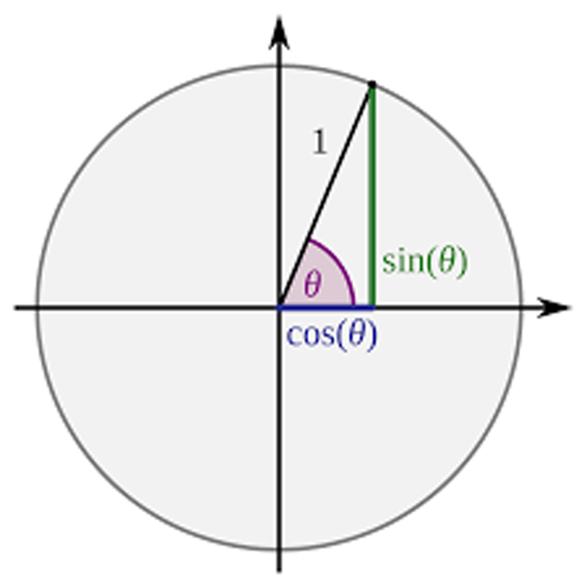
To aid in understanding the trigonometric functions as they relate to waveforms, this diagram is helpful:
The three sides of a right triangle are:
- Hypotenuse – The side going from angle θ to the circle, forming its radius
- Opposite – The side opposite to angle θ
- Adjacent – The side adjacent to angle θ, but not the hypotenuse
The most important trigonometric functions are the sine of angle θ, which is the ratio of the length of opposite over hypotenuse, and the cosine of angle θ, which is the length of the adjacent side over hypotenuse.
The circle is another way to represent a waveform. As the hypotenuse rotates in a counterclockwise direction, angle increases. The opposite side gets longer and the adjacent side gets shorter. This continues until the opposite side and the hypotenuse become vertical, at which point the opposite side is maximum. (The hypotenuse never changes, unless the amplitude of the signal changes).
At this point, the rate of change in the length of the opposite side is minimum, until the hypotenuse coincides with the horizontal line, when it is maximum.
Now, refer back to figure 1, which shows the sine wave in the time domain. Notice again that the rate of change is the minimum when the curve reaches the positive and negative peaks of the signal’s instantaneous amplitude, and the rate of change is greatest when the instantaneous amplitude is least, i.e., when it crosses the X-axis. This is the essential characteristic of the sine wave as well as many natural and human-made phenomena that conform to the sine wave. An example is the pendulum. It comes to a complete stop at its high point, then once more begins to accelerate.
The characteristic behavior of the sine wave is quantified in some relevant equations: Wavelength is the reciprocal of frequency, as in this equation: f = 1/T; where f = frequency in Hertz (formerly cycles per second), T = period, which is the time required for the signal to complete one cycle.
Angular frequency, denoted by ω (Greek omega), is the rate of change of angular displacement θ as in these equations:
Y (t) = sinθt = sin(ωt) = sin(2πft) and dθ/dt = ω = 2πf
Angular frequency = radians/s, which is 2π X Hertz.
Also, f = v/λ; where v = phase velocity and λ = wavelength.
For an electromagnetic wave moving through a vacuum:
f = C/λ; where C is the speed of light in a vacuum.
(Light does not actually travel at C. It approaches that velocity in a vacuum. In any other transparent medium, it travels at some fraction of C, which is responsible for the phenomenon of refraction.)
Modern elevators are powered almost exclusively by electric motors, but this was slow to become a reality. The first elevators were probably rope and basket affairs, going up the outside of buildings and powered by animals on a treadmill. The 19th century witnessed ever-accelerating industrial growth, and especially in cities where space was at a premium, buildings rose higher. Engineers sought ways to raise workers and materials above the traditional three stories. An important development was steam power and sometimes hydraulic, which at that time meant water.
When Edison, Tesla and Westinghouse appeared on the scene, electric power for elevators became a reality. Westinghouse invested heavily in Tesla’s new polyphase technology, with easily-reversible motors, but only Edison’s DC motor was really suitable. It also was easily reversible, merely by switching polarity, but the DC motor was far superior in elevator applications because speed could be controlled without overheating an AC motor, by simply reducing the voltage. Smooth speed control in an elevator is absolutely essential. The car must gradually slow down prior to stopping at each landing to avoid jolting the passengers. Also, the car has to move at reduced speed while in inspection mode during repairs and sometimes for fire-fighting operations. Tesla’s polyphase induction motor could do none of this, and for that reason, DC motors were used exclusively in elevator applications until the 1960s, with the introduction of the variable-frequency drive (VFD), which permitted speed and torque control of three-phase induction motors.
The person in the street probably believes that operation of a DC motor from an AC supply would require elaborate auxiliary equipment, but actually a simple rectifier is not a big deal, given the fact that diodes and capacitors may eventually need to be replaced. There is also the matter of brush replacement and possible commutator work in the DC motor, but overall, it is long-lasting and operates smoothly. In fact, during elevator overhaul, the DC motor with rectifier is often retained if it is working well.
Still, the AC motor with VFD has many advantages, and is used in all new construction, both for traction and hydraulic elevator systems.
VFD and AC motors are usually offered as a package, but it is conceivable that an off-the-shelf AC induction motor can be used. However, enhanced bearings and cooling must be considered for operation at other than rated speed.
When an elevator system fails to operate as intended, it is often the motor or control system that is faulty. Standard diagnostic techniques usually suffice to determine if the fault is in either of these areas. It is more often in the motor because that is where the moving parts are, and it is where the most heat is generated.
If the motor is still capable of running under load, a good way to start is to use the Fluke Thermal Imaging Camera or equivalent to check the motor and drive system, including the power supply terminations for overheating.
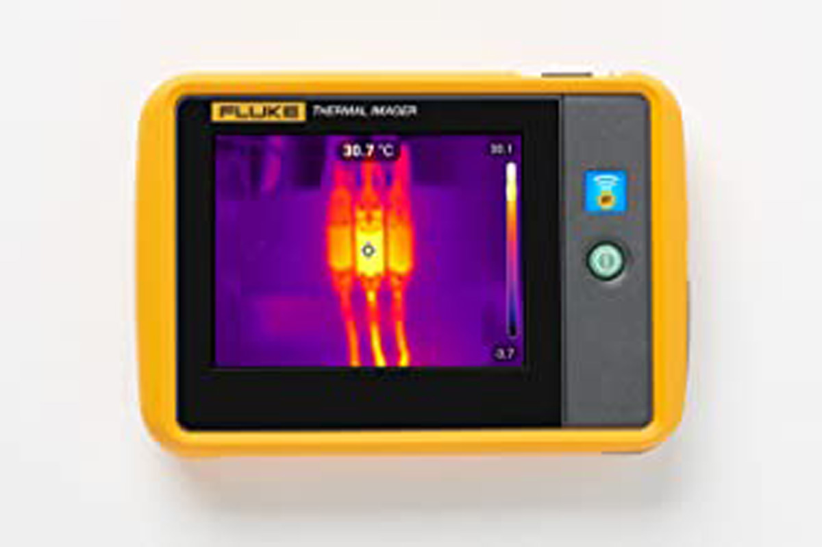
In diagnosing a motor/drive system, begin with the power supply. Usually, the motor is located in an elevator machine room adjacent to the bottom portion of the shaft and pit. A compliant installation will have an electrical disconnect in a metal enclosure located within sight of the motor. This disconnect should be labeled, and it can also be identified by the large power-supply conductors running (in conduit) from outside the machine room. From the disconnect, the output conductors, also in conduit, run through the motion controller and VFD to the motor. All of these terminations should be checked for unusual temperature rise, using the thermal imager.
Power to the motor can be interrupted at the breaker in the disconnect enclosure. The upper (input) lugs will still be live, and can be checked for waveform integrity, voltage and current, including phase balance. Current can be checked only with the motor running at full load. The electrical requirements of the motor (often about 30 HP) may be three-phase, 480 V or higher, so extreme caution is required in making electrical measurements. The dangers are electric shock from the high voltage and arc blast from a phase-to-phase or phase-to-ground short circuit.
Even a dry cement floor can have a strong ground potential, especially if it contains bonded rebar. It is best to lay a thick, dry rubber mat where you will stand. Insulated, dry boots are prudent, but they cannot be relied on because they may have an invisible slit or puncture holding moisture that would create a conductive path for current to ground. High-voltage gloves (available from Amazon) are also good protection.
Arc fault is a different type of hazard. Here, the human is not exposed to shock, but instead a low-impedance short, resulting, for example, from a dropped metal tool or slipped screwdriver bridging lugs at different potentials and causing the tool to vaporize with explosive force, spraying the hapless worker with molten metal. Additional precautions should therefore include a helmet and face shield. Multimeter probes should be of the high-voltage type with raised barriers to prevent the fingers from contacting live terminations. These precautions should always be in place when making power measurements from the input of the disconnect to the motor terminals.
In many instances, a VFD is equipped with a readout that displays fault codes. These will be listed in the manufacturer’s documentation along with suggested remedies. Error code F4, for instance, may mean that the drive is seeing an under-voltage condition, shutting it down. The failure can be in the drive, the motor or the supply voltage.
In all cases, a digital multimeter must be used within its rated voltage. For current readings, a non-contact clamp-on ammeter is the tool of choice. It is possible that voltage and current will read normal, but other types of waveform distortion could pose a problem.
After measuring voltage and current at the disconnect, they can be checked at various points throughout the VFD. Consult the manufacturer’s documentation for normal values.
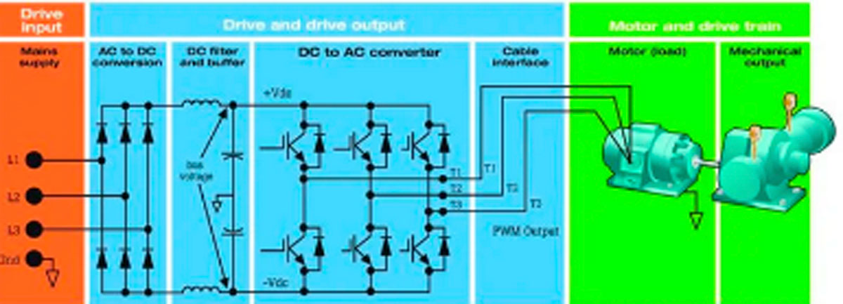
The next thing to look at is the DC bus. It should actually read higher than the peak-to-peak AC supply. How is this possible? The answer is that the DC bus voltage is the output of a full-wave rectifier. If the DC bus voltage is less than ideal, look back at the diodes and capacitors in the rectifier section. Another anomaly in the DC bus is excessive AC ripple. The multimeter should reveal ripple when the instrument is set on AC volts. A more definitive indication is provided by the oscilloscope. At this time, it is appropriate to go back to the disconnect and follow the three-phase path to the motor, looking at each test point using the oscilloscope.
Before commencing oscilloscope measurements, it is important to realize that the standard bench-type oscilloscope should not be used to look at the three-phase supply, DC bus or terminations at the motor. If this type of oscilloscope is used for these measurements and the ground return lead is connected to a wire or terminal powered by a voltage that is referenced to and floats above ground potential, there will be a low-impedance short back through the facility branch circuit to the system ground at the service. If you are fortunate, the light ground return lead will act as a fuse, burning out and interrupting the fault current. But otherwise, there is the potential for damaging the oscilloscope and/or VFD.
A solution is to use a set of differential probes, but they are very expensive and may not be available. A more workable answer is to use a hand-held, battery-powered oscilloscope operated within its rating with all channels insulated from ground and isolated from one another. Verify this detail in the operator’s manual.
To check a three-phase power supply or circuit, connect the ground return lead to the neutral terminal and measure the three individual phase conductors, with and without a load. These phases should be substantially the same voltage, within 3% with no load. If one phase is lower than the other two, it is possible that someone elsewhere in the building is bugging off a single-phase load. With the motor connected, it is not unusual to have one leg 5% lower than the others. Current imbalance can run a bit higher. Sometimes voltage imbalance is the cumulative result of motor and line imbalance — two low measurements affecting the same phase. In this case, rolling the connections at either input or output without reversing rotation (move A to B, B to C and C to A) may alleviate the imbalance. Using these and similar techniques, it should be possible to locate a line or VFD fault, or else isolate it to the motor, in which case motor rebuild or replacement might be indicated. All this is assuming the motor is still running and able to pull a load, as when the original complaint was a limited amount of heating in the motor.
As for oscilloscope readings, a major thing to look for are flat tops in one or more of the phases. This indicates that your machine is not processing the peak voltage and cutting it off at each cycle before the maximum is attained. This condition is also known as clipping. The flat tops may be either smooth or irregular (noisy) and this may tell you something about the nature of the fault. Another difficulty that is revealed in the oscilloscope display in one or more of the phases consists of small sine waves or what appears to be noise riding on the main waveform(s). This is a sign of harmonics getting into your otherwise harmonic-free power flow. It may be symptomatic of a load that is introducing distortion.
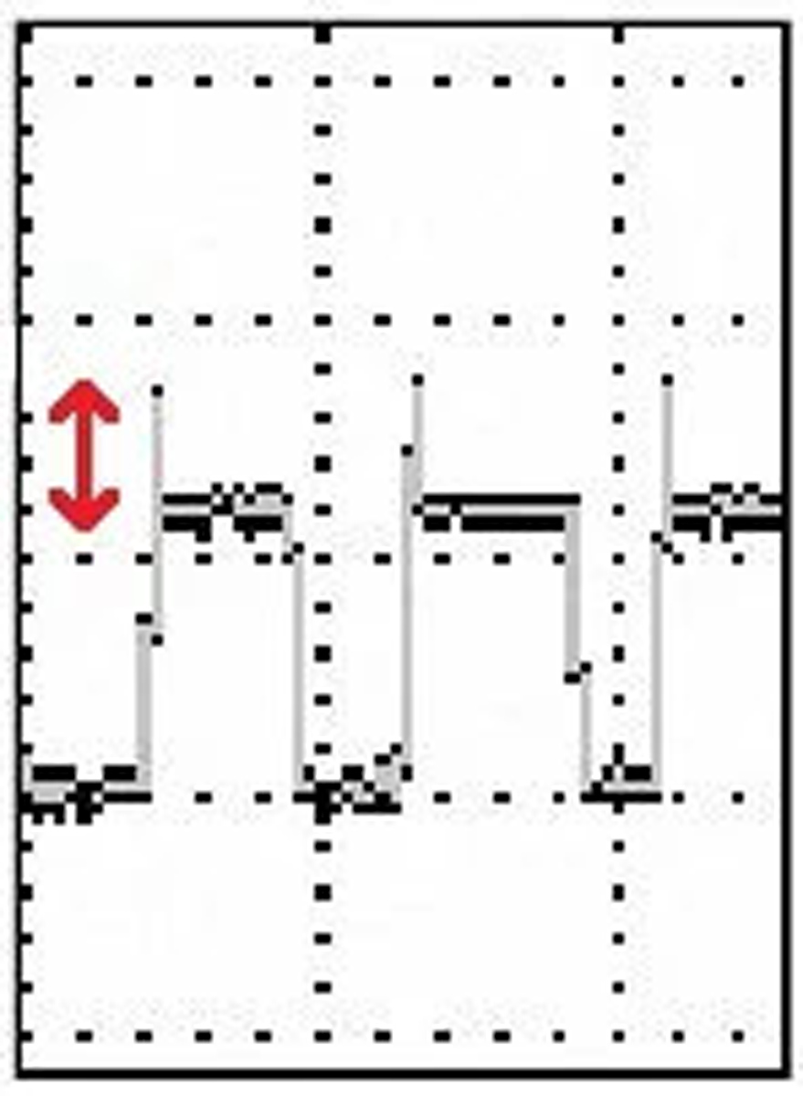
The final section of the VFD is the inverter. It consists of six SCR’s (silicon-controlled rectifiers) that convert the pure, ripple-free DC from the DC bus to the pulse-width-modulated square waves that feed the motor, permitting it to run faster or slower than rated without overheating (as if the sinewave supply were to be boosted or reduced).
These pulse-width-modulated square waves have varying duty cycles. A longer high time equates to higher motor RPM. The varying duty cycle is regulated by low voltage data inputs to the SCRs. The inputs are generated in the motion controller. They are capable of handling the high voltages and current required to power the motor.
What can go wrong?
Our primary task here is troubleshooting transient reflections that appear in the cable from the VFD to the motor. These transients may result from the fast-rising edges that are conveyed sometimes a substantial distance from the VFD to the motor. Various factors affect the sizes of the reflected waves, including cable length, motor load, surge impedance of the cable and motor and the spacing, rise time and amplitude of the pulses. Eventually, the reflected voltages can stress the cable and motor insulation, causing one or both of them to fail.
To diagnose, use the multimeter to check the excessive voltage at the motor terminals. Because of limited bandwidth, the multimeter may not reveal the full extent of the reflections, so again it is necessary to bring out the oscilloscope.
This kind of problem can be avoided by careful planning in the initial installation. The VFD should, in the initial installation, be located as close to the motor as practicable, so that the cable can be run directly with no bends. Even a slight pinch from a wiring staple, something that would not bother ordinary electrical wiring, can totally disrupt data cabling, especially if square waves with fast rise times are used to convey high frequency, high current energy. Consider placing the motor feed in grounded conduit to protect it from physical damage and interference.
Learning-Reinforcement Questions
Use the below learning-reinforcement questions to study for the Continuing Education Assessment Exam available online at Elevator Books or on p. 119 of this issue.
- What is a waveform?
- What is a trigonometric function?
- What are the three sides of a right triangle?
- How is a thermal imager used?
- Why is the DC bus voltage higher than the line voltage in a variable-frequency drive?

Get more of Elevator World. Sign up for our free e-newsletter.


