Elevator Car Plunges, Does a = g?
Aug 1, 2025

Exploring the potential causes and scenarios that make passengers feel as if the elevator is plunging
by Lakshmanan Raja
Recently, there have been reports on social media about elevator incidents mentioning that the elevator car suddenly plunged, causing passengers to be thrown into the air and injured. This article is an attempt to explore the potential causes and scenarios that could make passengers feel like the elevator is plunging during the ride. It will then focus on the specific cause of passengers being thrown into the air, as reported in the media. The analysis involves using physics equations and algebraic calculations to understand the situation. The scope of the article is limited to traction elevators, as these are the type of elevators commonly found in high-rise buildings.
Learning Objectives
After reading this article, you should have learned how to:
- Summarize the possible situation that causes the passengers to feel like the elevator is plunging.
- Review the physics equations and relevant code information necessary to analyze such incidents.
- Apply the kinematics equations and free body diagram to calculate the important quantities of the elevator such as acceleration and velocity under the incident situation
- Assess the energy imparted and its effect on the elevator passenger in such situations.
- Understand the importance of the brakes, speed governor, safeties and suspension system
Plunge in an Elevator
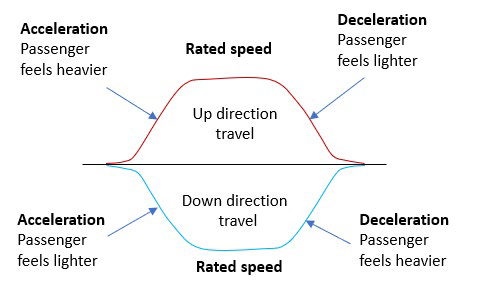
The main purpose of the elevator in a building is to move people up and down. Most modern elevators use some form of speed control system. During normal operation, the elevator accelerates to the rated speed, travels at the rated speed and decelerates when approaching the landing. This speed profile is shown in Figure 1. Passengers traveling in the elevator usually can’t feel the difference between a stationary elevator and one moving at a constant speed, i.e., the rated speed. Moving at a rated speed does not affect comfort, as the net force acting on the passenger is insignificant. Passenger comfort is affected by a change in speed (acceleration/ deceleration) because the net force acting on them is significant during that time. Their apparent weight changes during this acceleration and deceleration, as shown in the speed profile of Figure 1. Passenger internal organs move within the body frame, which also affects comfort. The industry practice for ensuring passenger comfort during normal operations is to limit the acceleration/ deceleration values of the speed profile to 1.2 m/ s2.[2]
In emergencies, passengers may experience higher acceleration/deceleration (retardation) which can make them feel a sudden change in their weight, almost like a plunge. Components, such as the emergency brake, driving machine brake, braking system, safeties and buffers, are used to slow down and stop elevators in such situations. The upcoming paragraphs will outline the code requirements concerning the retardation rating of these components. But first, there will be a recap of basic mechanics in the following section.
Value: 1 contact hour (0.1 CEU)
This article is approved for Continuing Education by NAEC for CET®, CAT® and QEI.
EW Continuing Education is currently approved in the following states: AL, AR, CO, FL, GA, IL, IN, KY, MD, MO, MS, MT, NJ, OK, PA, UT, VA, VT, WA, WI and WV | Canadian Province of BC & ON. Please check for specific course verification of approval at Elevator Books.
Basic Mechanics
We use basic mechanics to understand the impact of acceleration/deceleration on passengers. The equations used are:
| 1. Newton’s second law relates force to acceleration when the net force is not zero. Fnet = ma Fnet = Net force acting on a body m = Mass of the body a = acceleration of a body 2. Kinematic equations for one-dimensional motion with constant acceleration. vf = v0+ at vf = v02 + 2as xf = x0 + v0t + ½ at2 x0 = initial position; v0 = initial velocity xf = final position; vf = final velocity a = acceleration; s = distance; t = time; The actual weight of an object is the product of its mass and the gravitational acceleration, and it is measured in Newtons. When an elevator is in motion, the passengers experience acceleration and deceleration, as indicated in the speed profile in Figure 1. This causes the passengers to perceive a change in their weight, known as the apparent weight. |
| Actual weight = mg ( Newton) | ||
| Sign of ay | Up Direction | Down Direction |
| Acceleration | + (plus) | – (minus) |
| Deceleration | – (minus) | + (plus) |
Some possible situations that will use one of the below components or a combination to stop or slow down the elevator are explained in the next paragraph. When two components get activated simultaneously, then the overall retardation effect will be higher.
| Component | Relevant A17.1 – 2016 Rules | Retardation/ deceleration requirements |
| Emergency Brake | 2.19.3.2 (h) | On activation, car average retardation is not to exceed 9.8 m/s2 . |
| Driving machine brake | 2.24.8.3 (c) | Any deceleration not exceeding 9.8 m/s2 is acceptable. |
| Braking system | 2.24.8.2.2 | Any deceleration not exceeding 9.8 m/s2 is acceptable. |
| Type B Safeties | 2.17.3 8.2.6 | 0.35 g to 1 g (calculated from the min and max stopping distance from the governor tripping speed) |
| Type C safeties | 2.17.8.2.2 | On activation, car average retardation is not to exceed 9.81 m/s2. |
| Oil Buffer | 2.22.4.1.1 | Average retardation of not more than 9.81 m/s2 |
| Elastomeric buffer | 2.22.5.1 (a) | Average retardation of not more than 9.81 m/s2 |
Possible Causes
Passenger discomfort is mainly caused by higher acceleration and deceleration, making passengers feel like they are plunging. The effect of discomfort on each person depends on age, physical and mental health and whether that person is prepared for that experience.
Acceleration in the upward direction of travel and deceleration in the downward direction of travel will make the passenger feel heavier and increase their apparent weight (Figure 1). During this time, the passenger may step on the car floor harder. Their knees will absorb the impact, and if the acceleration/deceleration is very high, they may squat down.
Similarly, deceleration in the upward direction of travel and acceleration in the downward direction of travel will make the passenger feel lighter and decrease their apparent weight (Figure 1). During this time, the passenger will feel lighter and may step on the car floor more lightly. If this deceleration and acceleration exceed 9.8m/s2 (1 g), the passenger can experience floating in the air.
Electrical Protective Devices Activated in Rated Speed
While the elevator runs at its rated speed, certain electrical protective devices may get activated due to adjustment or wear issues. When these devices are activated, the drive machine brake and the braking system (if present) will engage, causing the elevator to come to an emergency stop with a higher deceleration than during normal operation. Especially for higher-speed lifts, the consequences are severe as the slowdown continues for more time until the car stops. It can happen in both up and down directions.
We commonly see this type of issue occurring when:
♦ The car door cam touches the landing door lock rollers due to misalignment, which opens the landing door contacts.
♦ The pressure of the landing door switch contact is inappropriate, causing it to open intermittently due to slight movements caused by wind pressure or someone touching the door panel from the lobby.
♦ There is an improper adjustment issue with the car door contact, emergency exit switch or car safety gear switch then it may open intermittently while the car is in motion due to vibrations.
Traction elevators use a counterweight to balance the cars. The counterweight equals the weight of the empty car plus 50% of the rated load. This means that, depending on the load inside, the car may become either heavier or lighter than the counterweight. During an emergency stop, the brake slows down the elevator car by using spring force, which remains fairly constant within its elastic range. Since the braking force is fixed, the deceleration caused by the brake and the stopping distance of the car depends on the load inside the car and the direction of its travel. When we assume the deceleration by machine brake as 0.3 g, then the apparent weight = m (g + ay# ) while decelerating by braking in the:
♦ up direction will be = 75(g – 0.3 g) = 75(0.7 g) = 52.5 g (passenger feels lighter as 52.5 kg)
♦ down direction will be = 75(g + 0.3 g) = 75(1.3 g) 97.5 g (passenger feels heavier as 97.5 kg)
As long as the passenger has some apparent weight, he or she will be standing on the car floor and won’t be flying in the air. However, this higher deceleration caused will make the passenger feel like the elevator is plunging.
The Elevator Machine Brakes or Worm Gear Engagement or Motor Gear Coupling Fails
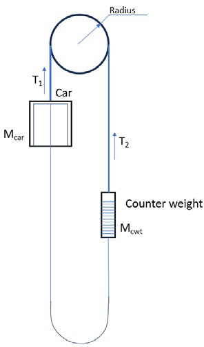
Since the counterweight in the traction elevators balances the car, the failure in the machine brake, worm gear or motor gear coupling, will allow the car to accelerate downward when it is loaded with more than 50% of its rated capacity. Referring to Figure 2, the sheave will turn anticlockwise.
In such a situation Mcar g > T and T > Mcwtg. Let us calculate the acceleration of the car for such a situation.
Referring to Figure 3 and Figure 4, applying Newton’s second law, we get:
From Figure 2, Mcara = Mcarg – T —————————(1)
From Figure 3, Mcwta = T – Mcwtg —————————(2)
By adding equation (1) and (2), we got Mcara + Mcwta = Mcarg – T + T ¬– Mcwtg
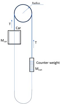 | 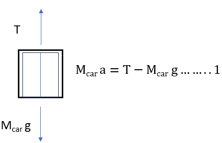 | 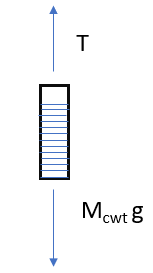 |
| Figure 2: Traction lift system Mcar = Car mass Mcwt = Counterweight mass g = acceleration due to gravity = 9.8 m/s2 | Figure 3: Free-body diagram of elevator car Mcarg = weight of the car T = tension on the suspension means. Note: For T = Mcarg, the car is stationary or moving with constant velocity. For T > Mcarg, the car accelerates in the up direction. For T < Mcarg, the car accelerates in the down direction. | Figure 4: Free-body diagram of elevator counterweight Mcwtg = weight of the counterweight T = tension on the suspension means. Note: For T = Mcwtg, the counterweight is stationary or moving with constant velocity. For T > Mcwtg, the counterweight accelerates in the up direction. For T < Mcwtg, the counterweight accelerates in the down direction. |
Taking out the common terms and simplifying
a (Mcar + Mcwt) = g (Mcar – Mcwt)
a = (Mcar – Mcwt) g/ (Mcar + Mcwt) —————————–(3)
If the car is loaded less than 50% of its rated capacity, as the counterweight is heavy, this will allow the car to accelerate in the up direction. In such a situation, T > Mcarg and Mcwtg > T.
Referring to Figure 3 and Figure 4, applying Newton’s second law we get
From Figure 2, Mcara = T – Mcarg —————————–(4)
From Figure 3, Mcwta = Mcwtg – T —————————–(5)
By adding equation (4) and (5), we get Mcara + Mcwta = T – Mcarg + Mcwtg – T
Taking out the common terms and simplifying a (Mcar + Mcwt) = g (Mcwt – Mcar)
a = (Mcwt – Mcar) g / (Mcar + Mcwt) —————————(6)
However, in the above calculation, we haven’t included the moment of inertia of the drive sheave. If we consider the moment of inertia of the drive sheave, then the tension on both sides of the sheave is not the same and is shown in Figure 5.
As the tension is not the same, for a lightly loaded car, T1 >Mcarg. The car will accelerate up, using Newton’s second law, and we get Mcara = T1 – Mcarg
Mccara + Mcarg = T1 ————————————(7)
Since the car accelerates up, T2 < Mcwtg, the counterweight accelerates down, and we get
Mcwta = Mcwtg – T2
T2 = Mcwtg – Mcwta ————————————-(8)
Now considering the rotational motion of the drive sheave; Net torque on the drive sheave = inertia of the drive sheave × angular acceleration ——————– (9)
Left hand side (LHS) of equation 9 can be expressed as: Net torque on the drive sheave = Net force (difference in tension) × the perpendicular distance (radius of the sheave)
Right hand side (RHS) of equation 9 can be expressed as: Inertia of the drive sheave = Mass × Radius2 (Note: We treated the drive sheave as ring)
Angular acceleration = linear acceleration / Radius = a/R
Now substituting back into equation 9, we get:
Net force (difference in tension) x the perpendicular distance (radius of the sheave) = (Mass of the drive sheave x Radius2) x a/R
As the car is lighter and it accelerates up, T2 > T1 (T2 – T1) Radius = Mass of the drive sheave × Radius2 × a/R Substituting the values of T1 and T2 from equations 7 and 8
(Mcwtg – Mcwta) – (Mcara + Mcarg) = Mass of the drive sheave × a(Mcwt – Mcarcar) g – (Mcwt + Mcar)
a = Mass of the drive sheave × a(Mcwt – Mcar)
g = (Mass of the drive sheave × a) + (Mcwt + Mcar) a(Mcwt – Mcar) g = (Mass of the drive sheave + Mcwt + Mcar) a
a = (Mcwt – Mcar) g/ (Mcar+ Mcwt + Mass of the drive sheave) ———(10)
Similarly for a heavier car case, the acceleration will be a = (Mcar – Mcwt) g/ (Mcar + Mcwt + Mass of the drive sheave) ———(11)
Equation (10) and (11) provide the expression for calculating acceleration during machine brake failure, worm gear engagement failure and motor-gear coupling failure with suspension means intact.
From those equations, we can deduce the following key points:
a) a = 0 when Mcar = Mcwt
• Acceleration will be zero when the car’s mass is equal to the counterweight’s mass. In this situation, the system is balanced and the net force acting on the car is zero.
b) a ≈ g when Mcar = 0 or Mcwt = 0
• Acceleration will be equal to or closer to gravitational acceleration only when either the mass of the car or counterweight is zero. This will happen only when the suspension breaks and the car and counterweight get separated. And in such a situation the car/counterweight will go into free fall.
c) For other situations, as long as the suspension means is intact, the acceleration of the car can never be equal to gravitational acceleration, and it will always be lesser than the free-fall acceleration of g.
Most suspension means failures are progressive, and it should be detected by the regular service visit if the maintenance is done properly. Hence, the likelihood of point (b) occurring is low. Let’s delve further into point (c) with an example.
Example
The rated load of the lift is 1000 kg, its balancing factor is 0.5, and the empty car mass is 1800 kg. The lift-rated speed is = 3 m/s and serves 20 floors. (Ground floor to 20th floor). The drive sheave mass is assumed to be 150 kg.
Situation 1 (Counterweight heavy) – The mentioned elevator was loaded with three passengers and each weighed 75 kg. It went down to the ground floor but didn’t open the door. The machine brake jammed on open condition and failed to hold the elevator car, and it started to accelerate upward since it was lightly loaded. The acceleration of the upward-moving car (using equation(10)) is
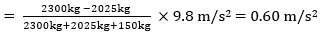
The apparent weight each person feels during the up-direction travel will be = 75(g + 0.06 g) = 79.5 kg (Passenger feels heavier.)
The elevator is accelerating up with an acceleration of 0.60m/s2. If the elevator is equipped with an Ascending Car Overspeed Protection (ACOP) feature, then it will trigger the emergency brake. The deceleration caused by the emergency brake is assumed to be 0.3 g then the apparent weight of the passenger is = 79.5(g – 0.3 g) = 55.65 kg. (Passenger feels lighter but won’t be flying inside the car.)
If we assume the ACOP stopping means it is not effective, then the car accelerates farther up. Let the height of each floor be 3 m. Hence, the travel distance is 60 m for 20 floors.
Now we know:
♦ the initial velocity is zero as the lift stopped at the ground floor before starting to accelerate up.
♦ the distance the elevator going to travel and its acceleration.
Then the final velocity is vf2 = v02 + 2as
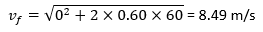
When the car is accelerating upward, the counterweight accelerates downwards and hits the buffer at a speed exceeding 8.49 m/s (due to the extra run-by distance). This speed is much higher than the buffer’s designed speed, which is 115% of the rated speed, causing damage to the buffer. Hence, the deceleration effect of the buffer can be ignored. This sudden stop (high deceleration) of the counterweight causes the car and passenger to jump. If the car is equipped with a compensation tied-down device, it will stop or reduce the car jumping to a certain extent (As per A17.1-2016 – 2.21.4.2, the compensation means, connection, building structural members and fastenings shall be capable of withstanding the maximum forces to which they are subjected due to car or counterweight buffer engagement or safety application with a factor of safety of not less than 2.5.).
The friction of the guide shoe, the weight of the traveling cable, stiffness in the steel wire rope and air drag on the car also play a role in reducing the car’s jump. However, these factors won’t prevent passengers inside the car from jumping, leaving them momentarily airborne. The height to which the passenger jumps is the difference between the car jump and the passenger jump. The following calculation considers the worst-case scenario, assuming the car stops abruptly without any jump.
Situation 2 (Car heavy) – Now we assume the same car is loaded with 10 passengers (750 kg), moving upward to the top floor due to the call, stopping at the top floor level, and not opening the door. The machine brake jammed on open condition, failed to hold the elevator and the elevator car started to accelerate down since it was heavily loaded. Acceleration of the car in its downward travel (using equation (11)) =
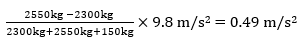
Apparent weight during the down-direction travel will be = 75(g – 0.049 g) = 71.33 kg (Passenger feels lighter). For the elevator with a rated speed of 3 m/s, when the speed goes beyond 3.52 m/s, the governor switch will activate the emergency brake. (Reference: ASME A17.1 2016 – Table 2.18.2.1)
The distance at which the emergency brake gets activated is calculated by using the formula
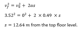
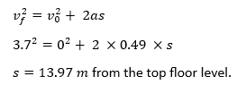
If the elevator doesn’t slow down, the governor will trip the safety mechanisms at 3.7 m/s. (Reference: ASME A17.1 2016 – Table 2.18.2.1) The safety mechanism will get activated by the governor at a distance of
If the safety mechanisms fail to grip the guide rails, then the elevator will continue to speed up, hitting the buffer at a speed higher than the intended, causing damage and abrupt stopping.
Learning-Reinforcement Questions
Use the below learning-reinforcement questions to study for the Continuing Education Assessment Exam available online at Elevator Books or on p. 124 of this issue.
- State the common causes that result in elevator plunging situations
- Not all plunging situation results in the passenger flying in the air. Explain.
- Explain how the empty elevator car’s mass and the elevator’s rated load affect the acceleration in uncontrolled situations.
- Calculate the final velocity of the upward traveling elevator when it crosses the top floor of a given building with the total number of floors and the floor height given.
- Explain the impact of the plunging situation on the passenger with the help of the energy conservation principle.
The speed at which the car hits the buffer is given by
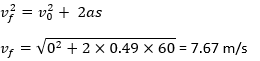
(Note: The speed will be more than this value due to the car run-by distance.)
As this speed is much higher than the buffer-designed speed, the deceleration effect of the buffer can be ignored. Once the car hits the buffer, it rebounds, and that rebounding distance depends on the rigidity and elasticity of the elevator car frame. Passengers will be pushed down onto the elevator floor due to increased deceleration in a downward direction. After the car hits the buffer, the possibility of passengers being thrown into the air depends on the energy absorbed by the elastic deformation of the elevator car frame.
Conclusion
The emergency stop at high speed can make passengers feel like they are plunging due to the intense deceleration. Suppose there is a failure in the brake or motor gear coupling. In that case, the car’s acceleration, whether ascending or descending, will always be less than the free-fall acceleration of gravity if the suspension system is intact. However, during high deceleration exceeding 1 g, passengers may feel weightless when their apparent weight becomes zero. This occurs when the counterweight crashes into the buffer at a speed higher than the buffer’s designed speed, leading to a car jump. This jump can also happen during a car collision with the buffer and due to the elastic deformation of the car frame. Our calculations are theoretical and assume constant acceleration; they do not account for elevator jumps during high deceleration. Nonetheless, they provide some insight into the acceleration experienced by passengers and the impact of being thrown into the air. Therefore, it is essential to regularly test and inspect the brake, safety systems and suspension system with the help of qualified elevator personnel.
References
[1] Young, Hugh D., Roger A. Freedman, and Albert Lewis Ford. University physics with modern physics. 13th edition.
[2] Barney, Gina, and Lutfi Al-Sharif. Elevator traffic handbook: theory and practice. Routledge, 2015.
[3] ASME A17.1-2016, Safety Code for Elevators and Escalators, American Society of Mechanical Engineers.

Get more of Elevator World. Sign up for our free e-newsletter.
![]()


 (1)")
![]()