
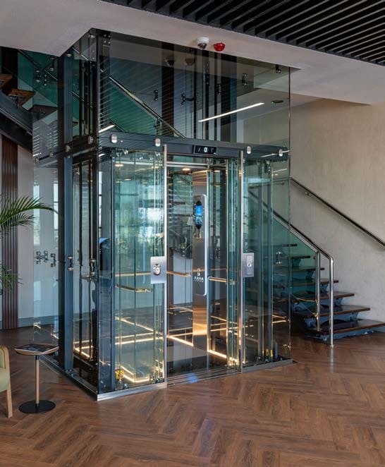
Panoramic passenger elevator at the EKA Elevator Factory in Türkiye
submitted by EKA
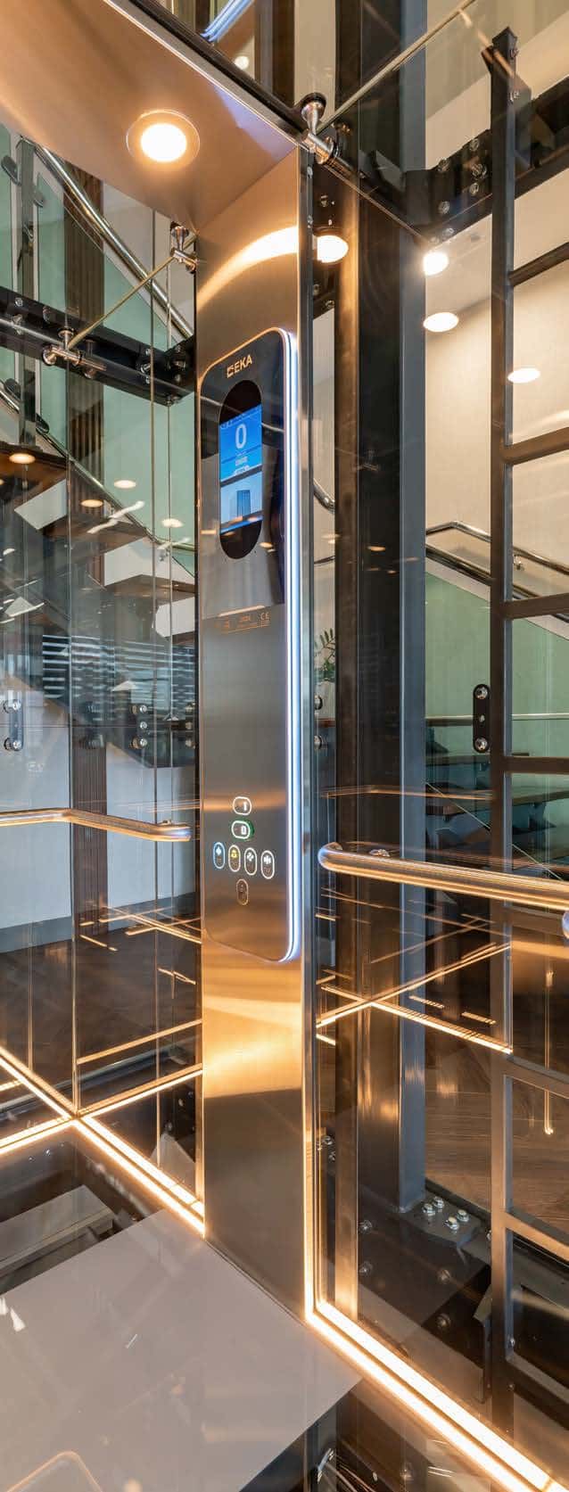
This elevator was designed with no visual boundaries between the cabin and the well or between the well and the world. Instead of stainless framed glass walls and doors, this elevator was designed with walls and doors made entirely of glass with glass-to-glass joints. Instead of using a steel construction structure carrying the system from four corners, we went beyond the norm and preferred a steel construction design built on two steel pillars behind the main rails.
With this project, we continue to direct the flow of life with our technology.
Specifications include:
- Complies with EN 81-20/50
- 825 kg
- Machine-room-less belt traction
- 1 m/s
- Two stops/openings
- Reduced overhead and pit
- Full glass panoramic elevator
The cabin was designed with a viewing angle of more than 90°. In order to increase the aesthetics of the structure housing it, the cabin floor and ceiling were also made of glass, ensuring integrity with the glass well walls. In accordance with EN 81-20/50 standards, a portable work area and railing system were designed for maintenance work to be carried out on the cabin. To preserve visual aesthetics, no external equipment was positioned on the cabin ceiling except for use in maintenance and malfunction situations.
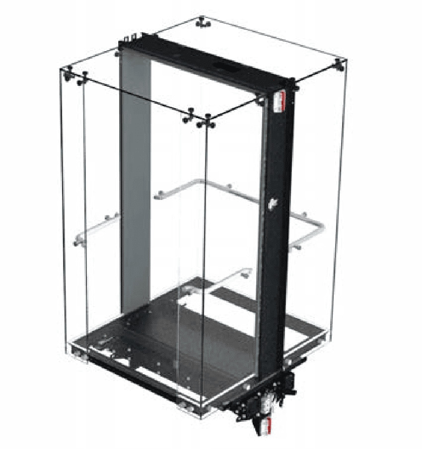
To increase the field of vision of the people traveling in the cabin, the steel shaft design also had to be optimized. Minimizing the visibility of the shaft steel from inside the cabin without compromising static calculations was the most challenging part of the design process. In this direction, 90% glass and 10% steel appearance were targeted.
In this context, instead of using a steel construction structure carrying the system from four corners, we went beyond the norm and implemented a steel construction design built on two steel pillars behind the main rails.
Due to this, it became necessary to plan the center of gravity of the entire system to be at the center of the steel tower pillars. At this point, the entire structure, including the carcass system operating in the shaft, the chassis system, the cabin, the external equipment above and below the cabin and the shaft windows, was established on a balanced system. Rather than considering this project a cabin design with a wide viewing angle, it would be more accurate to consider it a complete system design.
The steel structure built on two pillars was mounted on the floor concrete wall using correct supports and on the reinforced well walls prepared specifically for this project at the bottom of the well.
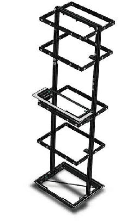
The support points mounted at the bottom of the well and on the floor were positioned using plumb and rope equipment to ensure 100% compatibility with each other during assembly.
The maximum error margin in the horizontal and vertical axis was targeted as 1 mm, and this target was achieved.
The support equipment not only provided the pillar assembly, but also played an active role in three different tasks. These are providing the balance of the structure, providing spigot support for the glass during the assembly of the well windows and fixing the floor doors on the steel structure without using a console.
With the awareness that even the smallest flaws can be noticeable, the steel tower, cabin, frame group, chassis and external components were manufactured at the Emlak Konut Elevator Konya Factory in Türkiye. The process selections for the equipment used were carefully determined. In order to prevent possible cosmetic errors during the manufacturing of the steel well equipment, all materials were manufactured with CNC (Computer Numerical Control) sheet metal cutting and CNC profile cutting machines. All equipment was stored under appropriate storage conditions until the assembly was completed.
Since welding processes can cause unwanted buckling or distortion in the materials, they were kept to a minimum during the production of the components. Ninety percent of the steel tower structure was realized with bolt assembly. A maximum tolerance of 1 mm was targeted in all measurements made during the assembly of the steel tower, and this target was achieved.
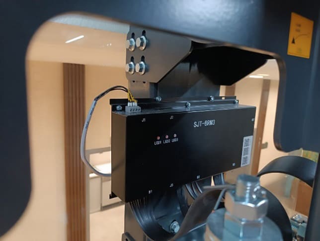
The first example of the “EKA S1 BELT” project carried out by Emlak Konut Elevator was implemented in this well. The machine, machine frame, cabin frame, weight frame and deadpoint systems were operated on this structure for the first time. In addition, all of the car operating panel, landing operating panel and LIP equipment were manufactured by Emlak Konut Elevator. All safety and comfort tests were carried out after the elevator was put into operation. All movements made with the existing elevator are controlled by a cloud-based control system, and the belt structure is monitored 24 h a day using a belt control unit.
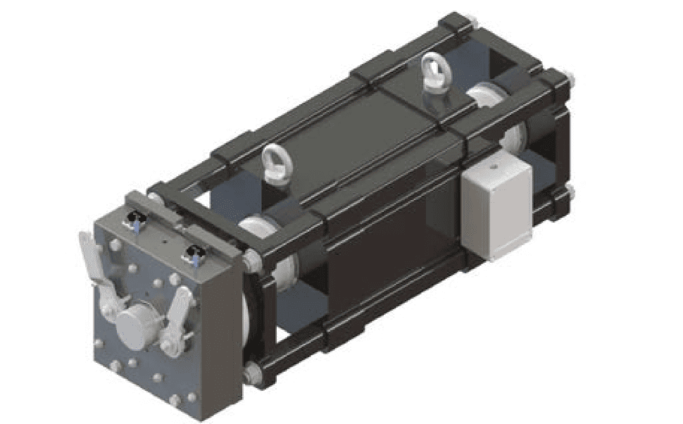
In line with the high comfort target, the elevator system is based on a belt-rope type structure. The machine is manufactured by Emlak Konut Asansör (EKA).
The reasons for choosing a two-belt belt type motor are to provide efficiency, comfort and balance. The two-belt structure is one of the necessary elements to maintain the balance of the steel tower by pulling the integrated cabin frame from the front and back of the rail axis.
In the drive system used in the elevator, optimization studies were carried out for the efficiency and torque fluctuations of the motor, considering elevator comfort, which is as important as efficiency.
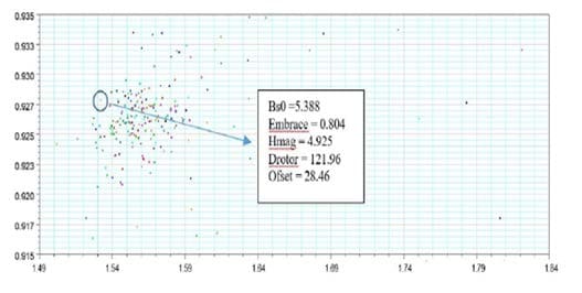
In the optimization studies, 92% and above efficiency and 2 Nm and below torque fluctuation boundary conditions were provided. In this direction, optimization of five different parameters —such as groove mouth opening (Bs0), magnet thickness (Hmag), pole spacing (Embrace), magnet edge shift (Ofset) and motor air gap (g) — was carried out with the genetic algorithm method. Figure 1 shows the distribution of optimization results.
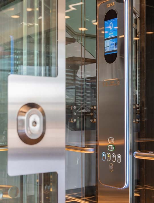
To make the cabin ceiling look more transparent and more spacious, the landing and cabin door mechanisms are designed to be at the bottom instead of the top. All systems on the mechanism are customized with 304 quality stainless steel or chrome-plated equipment. The aim here is to add a separate value to the visual integrity.
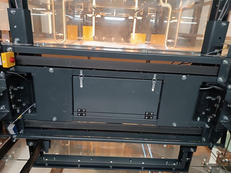
The cabin inspection box, which is normally on the cabin, is positioned under the cabin. Equipment such as skates, lift sensor magnetic tubes and oil cans, which are commonly seen on the cabin, are carefully hidden. Only a hand terminal is left on the cabin for maintenance personnel.
The same sensitivity was also shown inside the well. During the steel tower design phase, cable routes were determined inside the steel tower pillars and traverses for external installation elements (lighting, door contact installation, well bottom installation, button installation, etc.) and the well installation was completely hidden. To facilitate access to the installation in case of possible failure, hidden installation covers were placed on the steel structure.
Get more of Elevator World. Sign up for our free e-newsletter.
![]()


![]()