A New Method for Measuring Escalator or Moving Walk Overspeed and Anti-Reverse Protection
Mar 1, 2015

A testing system that uses an advanced single-chip microcontroller that can produce simulated overspeed and low-speed signals to test escalator or moving-walk protection
by Junhua Shen, Yihui Ruan, Rongfeng Lu and Jihnhua Ye
With the development of the economy and social progress in China, elevators, escalators and moving walks have become more and more important for everyday life. Accidents in which escalators and moving walks have run at reverse speed or at a very fast speed have occurred in recent years around the world, calling greater attention to riders’ safety. Now, most escalator and moving-walk manufacturers make use of speed sensors to monitor running speed in real time. A controller can receive the speed signals from these sensors and determine whether the units are running at a speed slower or faster than normal. For many controllers, low-speed protection is considered unintentional reverse running protection.
This article introduces a new testing system that can make use of an advanced single-chip microcontroller that can produce simulated overspeed and low-speed signals to test escalator or moving walk overspeed and anti-reverse protection. The model is characterized by simple structure, small volume, high response speed and high reliability.
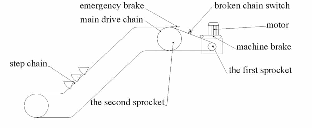
The design of the escalator or moving walk must demand that it will stop when it unintentionally runs in reverse or its rated speed exceeds 120%. To test the validity of the design, this method is studied to inspect overspeed and anti-reverse protection of the escalator or moving walk. This speed-measurement equipment includes an OEM-supplied stationary speed sensor. Though some sensors are fixed near the driving-chain sprocket, most are fixed near the flywheel. The measured targets are either holes or electromagnets. If these run face-to-face with the stationary speed sensors, the output of the sensors will be high or low. The output frequency of the sensor changes with the change of the escalator or moving walk speed.
The Principle of Measurement
If accidental reversing of an escalator or moving walk operating in the up direction happens, the unit will slow down, and its speed will be below 80% in the up direction, then above 120% in the down direction. At this time, the overspeed and anti-reverse protection device is activated, the motor is turned off, and the brake is activated, bringing the escalator or moving walk to a smooth stop. The speed sensor can monitor the flywheel or sprocket speed, as well as avoid reversing.
The speed sensor (proximity switch) is an automotive tachometer that generates a square waveform with a frequency proportional to the speed of the escalator or moving walk. When the unit is moving slowly, the sensor produces a low-frequency signal. As its speed increases, the sensor produces a higher-frequency signal. When the unit runs at normal speed, the output frequency of the sensor is a fixed value. Most OEMS simulate an overspeed or a low-speed signal to test overspeed and anti-reverse protection through parameter setup. However, different manufacturers have different testing methods. Equipment inspectors cannot be familiar with each. Meanwhile, inspectors cannot inspect the speed sensors; it is difficult to judge if the sensors are good or bad.
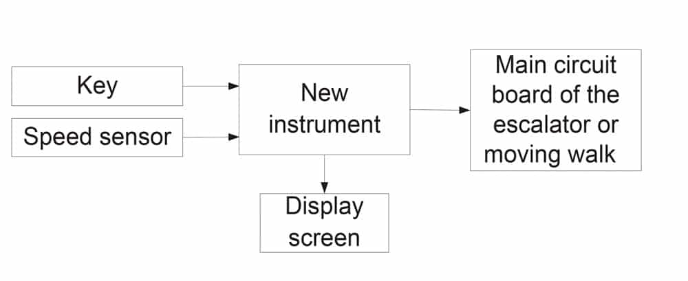
This instrument adapts the main circuit board, including a single-chip microcontroller, to receive pulse signals from a speed sensor. These signals are converted into an escalator or moving walk speed value and stored in the microcontroller’s memory. When an escalator or moving walk runs at a rated speed, the outputs of the speed sensor are fixed pulse signals. If an escalator or moving walk runs reversely, the output pulse frequency of the speed sensor will be different from the pulse of fixed-pulse signals. If the speed of a unit is higher than its rated speed, the output frequency of the speed sensor is higher than its rated frequency.
This microcontroller can produce more than 120% and less than 80% of its rated output frequency. The unit running speed is proportional to the output frequency of the speed sensor. The main circuit board utilizes these values to simulate overspeed and low-speed signals, putting them into the main circuit board of an escalator or moving walk. Inspectors can judge the unit’s overspeed and anti-reverse protection function from its operational status.
Hardware Composition
The system is composed of both hardware and software (Figures 2 and 3). The former component includes a single-chip microcontroller, key, display screen and detecting port. The core of the hardware is the microcontroller (model 89E564RD2). The microcontroller can be considered a self-contained system with a processor, memory and peripherals, and can be used as an embedded system. The device relates to a key input processing circuit for processing key input data and transmitting the processed data to the microcomputer. The output signals, which are generated by the microcontroller, are sent to the main circuit board of an escalator or moving walk. These signals simulate impulse signals generated by the unit.
When connecting the data terminal of the instrument to the output port of the speed sensor, the measured pulse frequency at normal speed, more than 120% and less than 80% of pulse frequency can be seen on the display screen. Inspectors can press “+” or “-” to acquire different pulse frequency and determine when the escalator or moving walk will stop.
Software Design
The C programming language is used when programming the single-chip microcontroller, which is powerful when processing data. Elevator inspectors can set up parameters by pressing “+” or “-.” The system can simulate overspeed and low-speed signals, which are proportional to the frequency of pulse signals generated by the speed sensor. The control software is implemented in the programming environment of µVision4.
Get more of Elevator World. Sign up for our free e-newsletter.


