Creep of Suspension Ropes
Mar 1, 2019

An examination of creep property (not to be confused with slippage) as it works on suspension ropes
This article focuses on the creep property of suspension rope. It analyzes its cause and properties, then discusses how to test the total creep of the rope. A reasonable amount of total creep is recommended for ropes on elevators. It also uses an actual case to show the importance of regular rope inspection that looks for total creep to monitor traction conditions and solve field failures.
As “elastic connecting units” for traction elevators, suspension ropes link the car and counterweight; meanwhile, as “power- transmission units,” they transfer the power flow from machine to car/counterweight to move the elevator up and down. So, their properties are very important to elevator performance, which can be measured as static and dynamic. The static properties like minimum breaking force and equivalent elastic modulus mean load-carrying capacity and rope stretch performance, respectively. The behavior of ropes in motion is defined as dynamic properties, such as longitudinal/lateral oscillation, bending and creep.
Creep
When the elevator is running, the suspension ropes relative to the sheave always tend to creep toward the side with more tension. It is important to understand the difference between creep and slippage. The former is one of the inherent characteristics of suspension ropes for traction elevators, and its essence is the difference between elastomer deformation under different tensions. But, as a failure phenomenon due to insufficient friction between rope and groove, slippage can be avoided and even eliminated.
The following will analyze the root reason of rope creep from the Euler formula. When the elevator is operating normally, no slippage happens between the rope and groove, and the rope tension on either side of the sheave shall conform to:
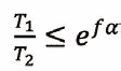
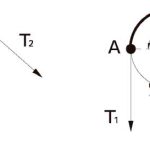
where e is the mathematical constant, and f is the friction factor.When the rope tensions on both sides of traction sheave T1 = T2, the tensile stress within the section of wrap angle shall remain unchanged. In this case, the traction system is presented as in a balancing state (Figure 1, left). Once the tension on both sides of the traction
sheave T1 > T2, within the section of wrap angle and from points “B” to “A,” the tensile stress will gradually increase from σ2 to σ1. As an elastomer and in the view of strain, the rope stretch will correspondingly increase from ε2 = σ2/E to ε1 = σ1/E after the rope travels over the traction sheave.
To analyze on the micro level, one elastic cell with a strain ε2 = σ2/E at “B,” after traveling across sheave and reaching “A,” achieves a change on strain ε1 = σ1/E and a difference strain Llε:
Llε = ε1 – ε2 = (σ1 – σ2)/E (Equation 2)
where E is the equivalent E-modulus of the rope (in MPa).
We can imagine that, after passing over the sheave, a rope cell becomes longer due to the tension difference, and, so, relative to the sheave, the rope tends to creep toward the side with more tension, T1, which is defined as creep property. From Equation 2, the dimension of creep is determined by the equivalent E-modulus of the wire rope and its tension/stress difference on both sides of the traction sheave.
To analyze on the macro level, if there is enough rope passing over the traction sheave, each tiny Llε will accumulate and eventually form a visible length error, defined as the total creep of rope.
To summarize and draw conclusions:
- The creep property is inherent of traction systems, which is similar to elastic slipping on belt-driven systems.
- The dimension of creep depends on two aspects: the elastic properties of rope (namely, the equivalent E-modulus) and the tension difference of rope on both sides of the traction sheave.
- The dimension of total creep is dominated by creep property and the length of the rope passing over the traction sheave.
- Slippage occurring between rope and traction sheave is a failure model, which can be avoided and even eliminated.
As a tiny deformation difference, it’s hard to observe or measure in a static state. However, the tiny differences accumulate until they form observable total creep. For an elevator designer, the total creep is more important than creep. Thus, the following will be focused on the total creep.
Total Creep
To define and measure total creep of the rope, stop the empty car at the bottom (or top) floor, draw a line with chalk or a marking pen on the rope and sheave at the section of their contact region, operate the elevator one cycle (trip) and go back to the initial position, so the marks on the rope and sheave are no longer in a line. We define the distance (as an arc of traction sheave) of the two marks as total creep of the rope. It should be noted that all analyses are made on ideal conditions — that is, without regard to possible slippage between the rope and groove.
To intuitively quantitatively analyze total creep, in a simplified elevator suspension model such as Figure 2, assume the parameter of elevator: pitch diameter of sheave D = 400 mm, and travel height H = 125.664 m. One trip involves the sheave dragging rope for 125.664 m. If the impact of rope creep is not considered, the sheave will rotate n = 125.664/(0.4 X 3.14) = 100 cycles.
Method of Measurement and How It Affects the Elevator System
After stopping the empty car at the bottom floor, take an overlap mark of “A” and “a” at suitable positions respective on rope and sheave (Figure 3). (To simplify analysis and explanation, the marked position is at the 9 o’clock mark on the sheave.)
Operate the elevator at normal speed, and lift the car from the bottom to the top floor. Based on the above hypothesis, the sheave will just rotate 100 cycles, and “a” will return to “initial position” (9 o’clock). Under the affection of creep property, the rope will move toward the T2 side (where there is more tension), the direction of which is the same with the rotation direction of the sheave (clockwise). Therefore, the sheave will not need to rotate 100 cycles (Figure 4).
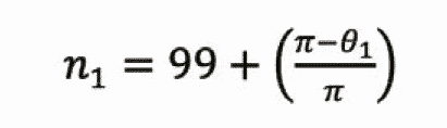
After the empty car arrives at the top floor, we can see that the mark “a” deviates the 9 o’clock (mark “Bb”) with an angle θ1. Hence, the actual rotation cycle of sheave n1 can be derived from:
Return the car to the bottom floor at normal speed in the downward direction (counterclockwise) from reference starting point “Bb.” The rope creep direction is constantly toward the T2 (clockwise) side, which is opposite to the rotation direction of the sheave. Thus, the sheave needs more rotation to the downward car relative to theoretical value.
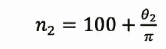
After the empty car returns to the bottom floor (Figure 5), “b” is beyond the theoretical position by angle θ2. This is because the reference starting point is “b” in the downward direction. Hence, the actual rotation cycle of sheave n2 can be derived from:
In an elevator system, the absolute position is determined by the roping of the car, so after one round-trip operation, the mark “A” on the rope is sure to return to its original position. However, the mark “a” on the sheave cannot, due to the influence of rope creep. From Figure 5, we can find that, relative to the rope or its original starting position, the sheave deviates an angle θ (θ = θ1 + θ2). This is defined as creep angle, and the corresponding arc length “Aba” is defined as total creep.
Direction
As mentioned, we do not mark “b” when measuring total creep. So, the total creep is the arc length of “Aa.” There are two different arc lengths from point “A” to point “a” along either circumferential direction. Thus, we need to confirm which direction is right to measure the total creep.
When testing with an empty car, which means the weight of the car is lighter than that of counterweight, T1 < T2, the direction of total creep is: the anticlockwise arc length “Aa” (Figure 6, left). When testing with full loads, which means the weight of the car is bigger than that of counterweight, T1 > T2, the direction of total creep is the clockwise arc length “Aa” (Figure 6, right).
This article assumes that the starting point is from the bottom floor. However, the result is the same as if we test it from the top floor. The dimension and direction of total creep will be the same.
To summarize above and draw conclusions on total creep:
- The dimension of total creep: after operating the elevator with one round trip, the displacement Lll is between the mark on the rope and the mark on the sheave.
- One round trip generates one total creep (Lll); therefore, after n time round trips, the total creeps are n X Lll.
- The total creep has not only dimension, but also direction, which always trends to the side with less tension.
- Within a certain period in which the traction condition is not changed, the dimension of rope total creep on the elevator will be stable and unchanged.
- The dimension and direction of total creep are independent of the initial position of the car.
- The creep angle θ is the sum of θ1 and θ2. Under ideal conditions, we consider θ1 = θ2 = θ/2, meaning the dimension is independent of the direction in which the rope runs.
However, in an actual elevator system with an empty car, the traction conditions are different between directions, so θ1 ≠ θ2. The difference is too small to observe, so it is normally not considered. The bigger concern is the dimension of total creep. There’s no need to accurately differentiate the two components.
It should be noted that the measured total rope creep by the above method is actually the “total creep of sheave.” Due to the property of an elevator system, the suspension rope (car) is always taken as the absolute position, which means the total rope creep cannot be observed. But, we can observe the total sheave creep, the dimension of which is equal to the former but opposite in direction.
The Normal Dimension
A clear understanding of total creep has been made according to the above analysis, but for an elevator, it is necessary to determine how many dimensions of total creep are in a reasonable region. To that end, this section will identify factors that affect the dimension of total creep.
The Equivalent E-Modulus of the Rope
The larger the E-modulus, the stronger the resistance against rope elongation and the smaller the rope’s total creep.
Load Difference on Both Sides of Sheave
The greater the rope tension difference on each side of the sheave, the more rope elastic elongation per unit length after passing over the sheave. Therefore, the greater rope total creeps. In an elevator system, the total creep is related to the rated load of the elevator. To determine whether total creep on a 1600-kg elevator is larger than that of an 800-kg, for example, consider that the dimension of total creep is not directly related to the capacity of the elevator. For the same rope type, safety ratio and travel height, the total creep is the same. That is because under the same safety ratio, the actual tension on each rope (of the same type) is the same, which means the same tension difference and the same rope total creep.
Rope Total Length Passing Over Sheave
The longer the rope passing over the sheave, the more rotating cycles the sheave has, and the larger the accumulated tiny rope creep and final total creep are. This is not only related to travel height, but also the suspension ratio.
For an elevator with a travel height of 100 m and suspension ratio of 2:1, after one round trip, the total rope length (2 X 2 X 100 = 400 m) passes over the sheave, which is the same as an elevator with a travel height of 200 m and suspension ratio of 1:1.
Normally, the rope total creep is proportional to the traveling height of the elevator. As such a conclusion is the default, these elevators adopt the same suspension ratio.
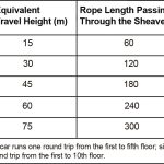
To verify the relationship of total creep with travel height, we test them on an elevator with a capacity of 1000 kg, suspension ratio of 2:1, floor/stops of 26/26 and travel height of 78 m (to simulate “different travel height”). The test result is shown in Table 1.
Based on the comprehensive consideration, for general-use elevators with a suspension ratio of 2:1, speed ≤ 2.5 mps and travel height ≤ 125 m, the recommended dimension of rope total creep is 20-60 mm, and the maximum should not exceed 80 mm.
Significance of Inspecting Rope Total Creep
Creep is an inherent property and unable to avoid, so why do we study it? As known, the rope creep caused by the traction drive only occurs on the traction sheave. The other pulleys of the elevator system (such as the reverse pulley on top of the car) do not have the creeping phenomena.
After an elevator is installed, total rope creep is a fixed value, which will be stable for the long term as long as there are no major changes to the traction conditions. So, best practice is to regularly check the total rope creep and monitor the traction conditions. Compare to previous total creep, and, once finding big total rope creep changes, check the traction conditions, such as groove wear. Note that “total creep” is the sum of total creep plus slippage.
The author once received complaints from a jobsite: after not being serviced in a long time, some elevators frequently appeared to have uneven-landing faults, which caused system crash and trapped passengers. According to an investigation and inspection, there were no failures on related components, but the total rope creep was 500 mm. The conclusion was that the traction was not enough, and serious slippage happened between the ropes and grooves. This led to the car always overpassing the destination landing, triggering trouble codes. It was proposed to replace the traction sheave with a new one with a different groove profile. After replacement, the total creep reduced to 45 mm, and the fault code disappeared.
Conclusion
This article analyzed the origin and properties of rope creep on traction elevators. The formation, rule and measurement of total creep were discussed in depth, and the reasonable interval of slip was given. Measuring the rope total creep of an elevator regularly can monitor the change in traction condition, which is greatly significant for fault prevention and early detection.
-
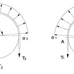
- Figure 1: Tensile stress in rope over the traction sheave: 1 = traction sheave; 2 = suspension rope; α = angle of wrap of ropes on traction sheave (in rad); T1 and T2 = forces situated at either side of the traction sheave (in kN); and σ1 and σ2 = tensile stress in rope on traction sheave (in N/mm2).
-
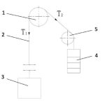
- Figure 2: Elevator suspension system model: 1 = traction sheave; 2 = suspension rope(s); 3 = car; 4 = counterweight; 5 = diverting pulley; T1 = rope tension on car side; and T2 = rope tension on counterweight side.
-
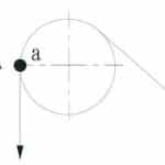
- Figure 3: The initial position when testing total creep: “A” = the mark on the rope, and “a” = the mark on the sheave.
-
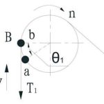
- Figure 4: The intermediate position when testing total creep: “B” = the mark on the rope when the car is at the top fl oor; “b” = the mark on the sheave; v = direction of car movement; n = direction of sheave rotation; and Θ1 = downward creep angle (in rad). Note that it’s not required to mark “B” and “b” for actual measurement; here, mark them only to facilitate analysis and explanation.
-
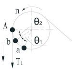
- Figure 5: The fi nal position when testing total creep: Θ2 = upward creep angle (in rad).
-
- Figure 6: The direction of total creep: θ = the creep angle (in rad).
-
- Table 1
References
[1] Peng Zhang. Theoretic and Test Research on Dynamic Behaviors of Elevator Suspension System, Shanghai Jiaotong University, Shanghai (2007).
[2] Jihu Bao, Peng Zhang and Changming Zhu. “Longitudinal Vibration of Rope Hoisting Systems With Time-Varying Length,” Journal of Vibration and Shock, 32 (15): p. 173-177 (2013).
[3] Tianxiao Ren. “Optimization of Traction Conditions on Elevator,” Journal of China Elevator, 13 (5): p. 19-22 (2002).
[4] Congjian Zhu. “Influence Analysis of Elastic Slippage in Belt Drive,” Journal of University of Shanghai for Science and Technology, (4): p. 92-98 (1993).
[5] Chao Xu. “Comprehensive Analysis of Elastic Slippage in Belt Drive,”
Journal of Modern Machinery, (2): p. 49-52 (2002).
[6] Wolfgang Scheunemann, Wolfram Vogel and Thomas Barthel. “Steel Wire Rope for Traction Elevators: Part Three.” ELEVATOR WORLD, September 2009: p. 95-106.
Get more of Elevator World. Sign up for our free e-newsletter.


