Electrically Based Intelligent Escalator Braking Systems
Apr 6, 2023

by Kevin Seaborne, Lutfi Al-Sharif and David Austin
Value: 1 contact hour (0.1 CEU)
This article is approved for Continuing Education by NAEC for CET® and CAT®.
EW Continuing Education is currently approved in the following states: AL, AR CO, FL, GA, IL, IN, KY, MD, MO, MS, MT, NJ, OK, PA, UT, VA, VT, WA, WI and WV | Canadian Province of BC & ON. Please check for specific course verification of approval at Elevator Books.
Learning Objectives
After reading this article, you should have learned about:
- The importance of an escalator braking system
- A braking system’s two conflicting requirements
- The main problem of conventional braking systems
- Types of intelligent braking systems
- The benefits of electrically based intelligent braking systems
Abstract
The braking system of an escalator is the most important safety device, as all other safety devices rely on it to bring the escalator to a complete standstill. Most escalators employ conventional open loop braking systems that apply the same braking force regardless of the load on the escalator and the direction of travel. This leads to large variations in stopping distance, but more importantly, it causes a severe stop under light loading conditions. The consequence of this is the high risk of passenger falls under light load stopping conditions, with consequential injury. The European escalator standard EN 115:2008 stipulates that the maximum value of deceleration measured in the direction of travel must be less than 1 m/s2. The motivation for this clause is to reduce the risk of passenger falls. Public service escalators carry larger numbers of passengers and are thus at a higher risk of passenger falls and especially avalanche falls. This paper describes the design, implementation and testing of an electrically based intelligent braking system applied to a public service escalator that significantly reduces the risk of passenger falls and meets the requirements of the standard. Of particular importance are the backup systems and the risk assessments implemented to provide the necessary safety assurance and ensure safe operation in the case of system failure.
Introduction
The braking system within the escalator is, in effect, the most important safety device. All other electrical safety functions rely on the braking system to bring the escalator to standstill. Loss of the functionality of the braking system will result in the loss of all other electrical safety features and will lead to a dangerous situation developing within the escalator.
A braking system must achieve two conflicting requirements: stopping the escalator within an acceptable distance to prevent injury (e.g., passenger entrapment) and not stopping too harshly to cause passenger falls. This is the dilemma facing the designer of the braking system. On public service escalators, this is even more critical due to the large number of passengers (as high as 58,000 passengers per day in some cases) [1]. In fact, the main motivation for developing intelligent braking systems on escalators (and especially for public service escalators) is the requirement to address the issue of passenger falls due to the abrupt stopping of the escalator.
It is worth remembering that the majority of stops on escalators are unplanned stops, usually following the activation of a safety device. For this reason, a passenger traveling on an escalator never expects it to stop (as opposed to an elevator that stops at every landing). Consequently, many passengers do not hold the handrail, and this point further increases the importance of ensuring that the escalator stop is not abrupt.
This paper describes the development and testing of an electrically based intelligent braking system for public service escalators. The system ensures a gentle stop while still meeting the stopping distance requirements set by the standards for the full load in the down direction. The design of the system also ensures that failures within the system are anticipated and will not lead to a dangerous situation.
The main problem of conventional braking systems is discussed in the next section. The types of intelligent braking systems are then overviewed in the following section. The benefits of intelligent escalator braking systems are then outlined. This is followed by an overview of the principle of operation of electrically based intelligent escalator braking, and then the design and risk assessment of the system. The results of the site tests on the first escalators fitted with the system are then presented.
Conventional Braking Systems Versus Intelligent Braking Systems
Most public service escalators have two mechanical brakes: the operational and the auxiliary brake. The operational brake usually acts on the motor shaft. The auxiliary brake acts directly on the escalator main drive shaft (thus protecting against a drive chain failure). These two brakes comprise the current conventional braking system.
Conventional escalator braking systems apply the brake immediately and fully as soon as the safety line is interrupted. They rely on mechanical brakes to bring the escalator to a stop. For obvious safety reasons, the brake is always a mechanical brake that is spring applied and power lifted (either hydraulically or electromagnetically). The fact that the brake is spring applied ensures that the brake will still apply in the case of a power failure or control system failure.
The main problem with conventional braking systems is they have to cope with a number of varying parameters. These include the direction of travel (up and down); load (no load to full load); wear in the brake pads/shoes; changes in temperature and contamination of the brake pads/shoes. The brakes are usually designed/adjusted to deal with full load in the down direction such that the stopping distance does not exceed the value set by the standards (e.g., 1500 mm for a 0.75 m/s escalator).[2] However, this setup results in a sharp stop when the escalator is stopped under no load conditions, as well as a very short stopping distance when the escalator is loaded in the up direction. Once adjusted and set, the torque applied by the conventional braking system is the same regardless of the load on the escalator or the direction of travel. The abrupt stop that results under no load conditions can lead to passenger falls. If the torque setting on the mechanical braking system is reduced in order to reduce the abruptness of the stop and eliminate the risk of passenger falls, the escalator will fail to stop the full load in the down direction within the required stopping distance set by the standards.
This is the dilemma of the escalator braking system. Thus, the main motivation of developing an intelligent braking system is the urgent need to address the problem above and eliminate the risk of passenger falls while still meeting the stopping distances stipulated by the standards. The relationship between the risk of passenger falls and the kinematics of the stopping escalator has been comprehensively investigated in [3] and [7]. It has been shown that the maximum value of deceleration during a stop is the best indicator of the risk of passenger falls. The use of the maximum value of deceleration during a stop as an indicator of the risk of passenger falls on an escalator has now become widely used within the industry and is incorporated in standards [2] and [4]. The use of intelligent braking systems is one of the most successful methods of meeting this maximum deceleration requirement.
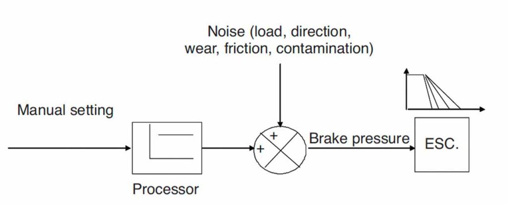
A conventional braking system is a form of open loop control system, as shown in Figure 1. The torque from the brake is set to a specific value, and thus any variation in the “disturbance” parameters would lead to large variations in output. The output in this case is both the value of deceleration and the value of stopping distance.
Intelligent braking systems, on the other hand, apply the braking torque to the escalator in a gradual fashion, over a period of time, in order to allow a gradual and controlled stop. The systems can be set to keep the deceleration constant or the total overall stopping distance constant, both of which are interrelated.
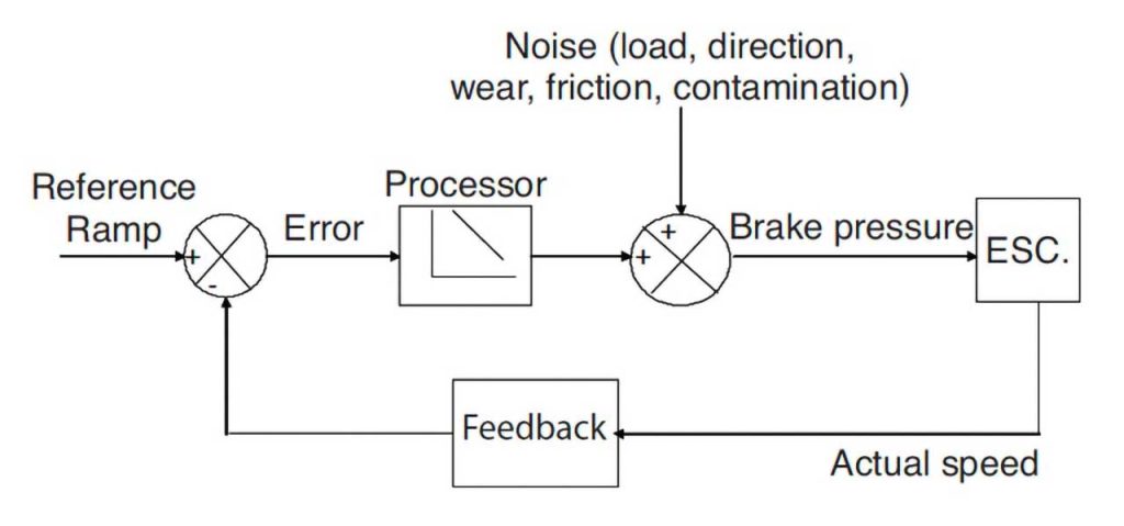
An intelligent braking system monitors the value of the variable it is trying to control (speed in this case) during the braking sequence. It then continuously adjusts the braking effort to follow the set speed curve. Even if a “disturbance” is introduced into the system (in the form of a varying load for example), the feedback loop feeds this information to the system, and the braking effort is changed to suit. This is an example of a closed loop system (Figure 2).
As seen from the discussion above, an intelligent braking system requires the means to vary the braking torque depending on the load and direction conditions prevalent during a braking cycle. There are two different technologies to achieve this variation, as discussed in the next section.
Types of Intelligent Braking Systems
Intelligent braking systems generally fall into two categories: hydraulically based and electrically based.
Hydraulically Based Systems
Hydraulically based systems require that one of the conventional brakes be hydraulically lifted. Hydraulic systems control the hydraulic pressure lifting the brake pads off the disk. This can either be done using a linearly proportional valve or using on/off modulation by varying the duty ratio (i.e., on/off ratio). Hydraulically based intelligent braking systems are beyond the scope of this paper. They are discussed in more detail in [5].
Electrically Based Systems
Modern escalator control systems are equipped with variable speed drives that are used for starting the escalator and running it at different speeds during the day. This drive can also be used to implement the intelligent braking function. Electrically based systems employ the variable speed drive (usually a VF drive) to bring the escalator to a standstill and then apply the mechanical brakes as holding devices. In this case, the mechanical brakes that are used for conventional braking become merely parking brakes applied once the escalator has come to a standstill. The inverter used on this system does not employ closed loop feedback, and it relies on the fact that the motor will follow the speed that is set by the frequency sent by the drive.
Benefits of Electrically Based Intelligent Braking Systems
The benefits of electrically based intelligent braking systems fall into three main categories:
- Reduction of the risk of passenger falls: The most important benefit of an electrically based intelligent braking system is that it can closely control the profile of the stopping speed-time curve. This allows the system to accurately control the value of the maximum deceleration, which is strongly correlated to the risk of passenger falls.[3] This maximum deceleration requirement is also an EN 115 standard requirement, and thus, the electrically based intelligent braking system ensures compliance with the European standard. It is worth noting that, based on past practical experience, meeting such a requirement is extremely difficult with a conventional braking system.
- Ability to differentiate between different types of safety device trips: As any safety device stop would be initiated by the programmable controller in the form of a signal sent to the variable speed drive, it is possible to vary the stopping distance and the value of maximum deceleration depending on the nature of the safety device initiating the stop. As an example, the stopping distance requirements in response to a comb switch tripping will require a shorter stopping distance compared to an over-speed protection device. In the former case, preference will be given to a shorter stopping distance provided the value of maximum deceleration is within limits, while in the latter case a low value of the maximum deceleration would be preferable with a longer stopping distance. This feature can be referred to as the Safety Device Differentiated Stopping Distance (SDDSD). This feature has not been implemented on this system at this stage but will be considered in future versions.
- As the mechanical brakes are only used as parking brakes, lower wear rates will be sustained. However, this does require regular checking of the performance of the mechanical brakes (e.g., during six monthly inspections).
Principle of Operation of Electrically Based Intelligent Braking Systems
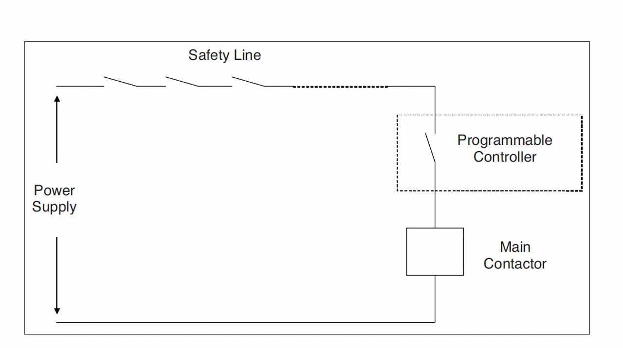
A block diagram of a conventionally based braking system is shown in Figure 3. The safety line acts directly on the final contactors (albeit through the contacts of the programmable controller). As soon as any safety device trips, the main contactors trip and thus remove power from the drive motor and apply the mechanical brake.
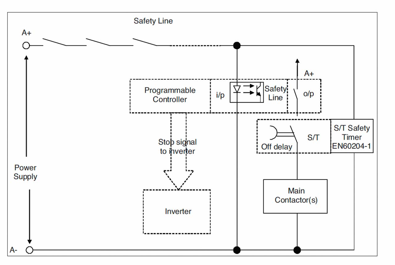
Electrically based intelligent braking systems, on the other hand, interpose the programmable controller between the end of the safety line and the main contactors. As shown in Figure 4, the safety line feeds its signal into the programmable controller when a stop is required. The programmable controller then sends a “ramp down” command to the inverter and keeps the main contactor(s) activated until the escalator has come to a stop, where it then trips the main contactor(s) and applies the mechanical brakes as parking brakes. As a backup feature, two safety timers are used that are triggered by the interruption of the safety line and cause the brakes to apply at the end of a specific period regardless of whether the escalator has stopped or not.
So, the sequence of events during a stop can be summarized in the following two parallel paths. Once a safety device trips in the safety line, a signal is sent to the programmable controller and the safety relay simultaneously. The programmable controller sends a signal to the variable speed drive to ramp the speed down. Once the escalator has come to a standstill, the mechanical brakes are applied as parking brakes. During this time, the safety timer is timing down and will apply the mechanical brakes if the escalator has not come to a standstill by the end of the specified period of time. This is necessary to protect against a failure within the programmable controller or the variable speed drive.
It is worth noting that the use of the variable speed drive as a means of braking is not a new concept and has, in fact, been used in elevators for the last 30 years. However, the reasons for the delay in applying it to London Underground escalators are as follows:
- The safety standards have traditionally required that the safety line act directly onto the main contactors driving the motor. Such a requirement makes it impossible to employ electrically based intelligent braking. This requirement was dropped in EN 115:2008 and is no longer an obstacle to the implementation of the electrically based intelligent braking system. [2, 6] There is a fundamental difference between the use of electrically based intelligent braking systems in elevators and escalators. The majority of elevator stops are functional stops at landings, and in these cases the use of electrically based braking is accepted by standards. However, the majority of stops of an escalator are safety device stops, and in these cases the use of electrically based braking has only recently become allowed by the standards (as discussed in the previous point).
- The requirement for a high level of integrity of the system overall. Assurance must be provided that shows that in the case of failure of any component, such a failure will not lead to a dangerous situation. This has been addressed in the next section.
System Architecture
The last section outlined the basic architecture and the principle of operation of a basic electrically based intelligent braking system. This section analyzes the possible system architectures in detail, carries out a high-level risk assessment and recommends extra protection measures.
The approach that has been taken is as follows:
- Building the system from basic blocks and assessing the risk caused by the failure in any block.
- If any single failure leads to a dangerous situation, the system must be enhanced to eliminate it.
- The steps above are repeated until no single failures that lead to a dangerous situation remain.
The advantage of dealing with the system components as large blocks obviates the need to examine the software within these blocks in any detail. The risk assessment ensures that the system is tolerant of any fault within the block under consideration whether that is a hardware or software fault.
It is important to emphasize that this approach is not an alternative to a detailed risk assessment from the manufacturer around this system.
Structure of the System
Following several iterations, an optimum architecture for the system was arrived at that further ensures that a failure in any component of the system will not lead to a dangerous situation. This final system is outlined in this section.
Further analysis of the basic system discussed in the last section shows that, in the case of failure of the controller or the drive, the escalator will continue running following the receipt of a stop signal for around 2 s until the safety timer applies the brakes. At a speed of 0.75 m/s, the extra distance traveled is 1500 mm, which is excessive and could lead to a dangerous situation. So, the following enhancement to the system was introduced. All modern London Underground escalator control systems comprise two programmable logic controllers: the main controller and the auxiliary controller. The two controllers fulfill the requirement for redundancy in the detection of step and handrail over-speed and under-speed functions. To do this, both controllers independently receive the escalator actual speed signal, and thus are ideally placed to provide an extra checking mechanism that could address the limitations of the basic system discussed in the last section.
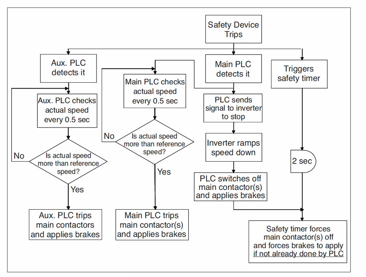
Each controller checks the speed of the escalator at regular intervals following the tripping of a safety device. The controllers compare the actual speed of the escalator to a hypothetical “envelope” curve, to ensure that the escalator is slowing down. If either controller detects a discrepancy at any point, it will trip the main contactors and apply the mechanical brakes. This extra checking is shown in flowchart format in Figure 5.
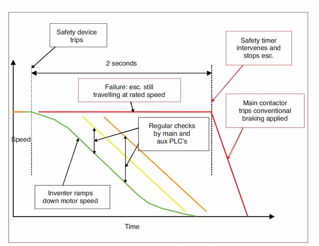
Figure 5 also illustrates the various lines of defense (functional; first line of defense using the safety timer; second and third lines of defense provided by the programmable controller checking function). This is also shown in timeline diagram (as a speed-time profile curve) in Figure 6.
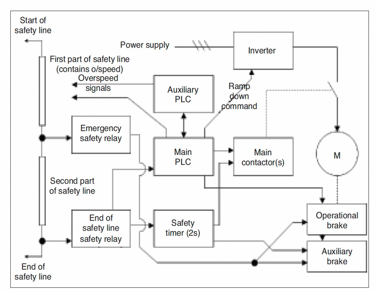
A block diagram of the various components and connections of the complete system is shown in Figure 7. The components are given descriptions of generic nature. The block diagram shows the extra connection from the end of the safety line to the auxiliary programmable controller to provide the independent signal necessary to allow the auxiliary programmable controller to carry out the speed curve checking function.
Safety Consideration
There are three salient points that emerge from the approach to developing the system:
- A number of lines of defense have been built within the system to ensure that, in case of failure of one line of defense, the system resorts to the next line of defense.
- In case of failure of the electrically based braking system, the controller can revert to a conventional braking system.
- Regardless of the above, an FMEA (failure modes and effects analysis) needs to be carried out on the system to ensure the following EN 115 safety premise is always met: One single fault within the system should not lead to a dangerous situation. If one fault has been detected, the system should not restart at the next cycle and an error should be raised. [2, 6]
An FMEA involves assessing all the possible failure modes, identifying which faults lead to a dangerous situation and modifying the design to eliminate the risk arising from such failures. This FMEA has been carried out on the electrical and mechanical parts of the system. As a simple example, the loss of the feedback connection should not lead to a dangerous situation and should result in the system stopping and raising an alarm.
Pass/Fail Criteria for Electrically Based Intelligent Braking Systems
The pass/fail criteria for any braking system will fall into two main categories: stopping distance and maximum deceleration during the stop.
- Stopping distance: This is usually specified as a minimum value of stopping distance at no load and a maximum value of stopping distance under full-load conditions in the down direction. As an example, for a rated speed of 0.75 m/s, the minimum stopping distance under no load conditions is 400 mm, and the maximum stopping distance of 1500 mm under full-load conditions in the down direction.
- Maximum deceleration during the stop: The maximum deceleration during a stop is the best indicator of the risk of passenger falls. This is currently set at a maximum value of 1 m/s2 in the direction of travel (low pass filtered at 4 Hz).
The rationale for the maximum stopping distance requirement is the protection of passengers following an entrapment. The rationale for the minimum stopping distance requirement is the reduction of the risk of passenger falls, although this is a very crude method of ensuring this. Historically, the second criterion (i.e., maximum deceleration) is a relatively new requirement. In effect, the use of maximum deceleration is a much better indicator of the risk of passenger falls than the minimum stopping distance. However, the minimum stopping distance requirement remains in the standards.
For an electrically based intelligent braking system, achieving the maximum deceleration criterion is straightforward. As the electrically based intelligent braking system can effectively achieve the same stopping distance under full-load and no-load conditions, it is more appropriate to state the stopping distance criterion as one stopping distance with a tolerance. For example, it can be stated that the system can achieve a stopping distance of 1100 mm ±20 mm.
Test Results
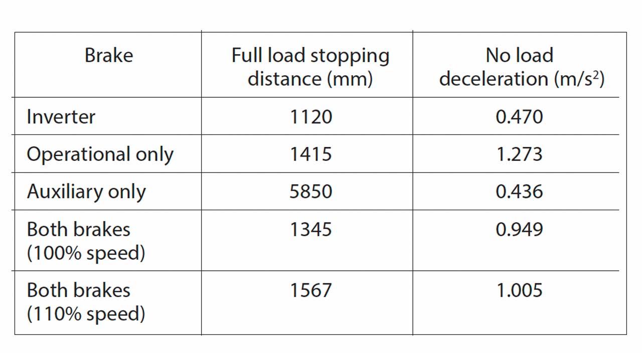
Following the design and implementation of the system, the first site tests were carried out in July 2009. The results from the weight tests are shown in Table 1. For each braking scenario, the full load stopping distance is shown, as well as the no load maximum deceleration value (post weight test).
The maximum deceleration values were measured using the accelerometer on the EVA625 unit manufactured by PMT (sampled at 256 samples per s and low pass filtered at 4 Hz in the combined X and Z axes in the direction of travel). The values of maximum decelerations shown in the table are taken from these accelerometer readings.
In addition to the accelerometer reading, a second eva625 unit was used to measure the speed-time profiles for information. The speed profiles were measured using the hand-held tacho-wheel unit with the EVA625 device. The sampling frequency of the hand-held tacho-wheel is 64 samples per s. The unit has an on-board low pass filter of 4 Hz.
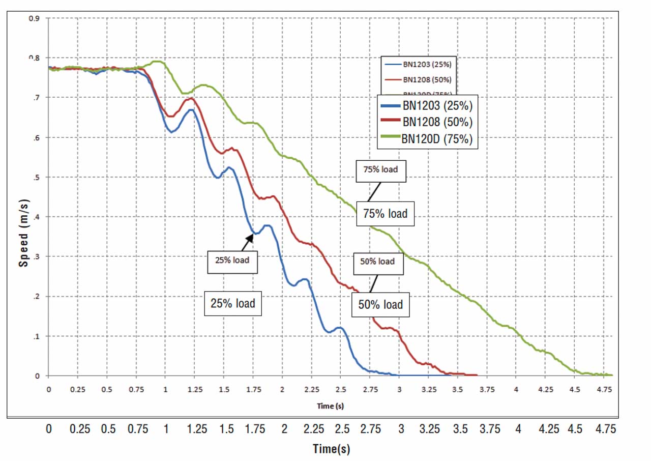
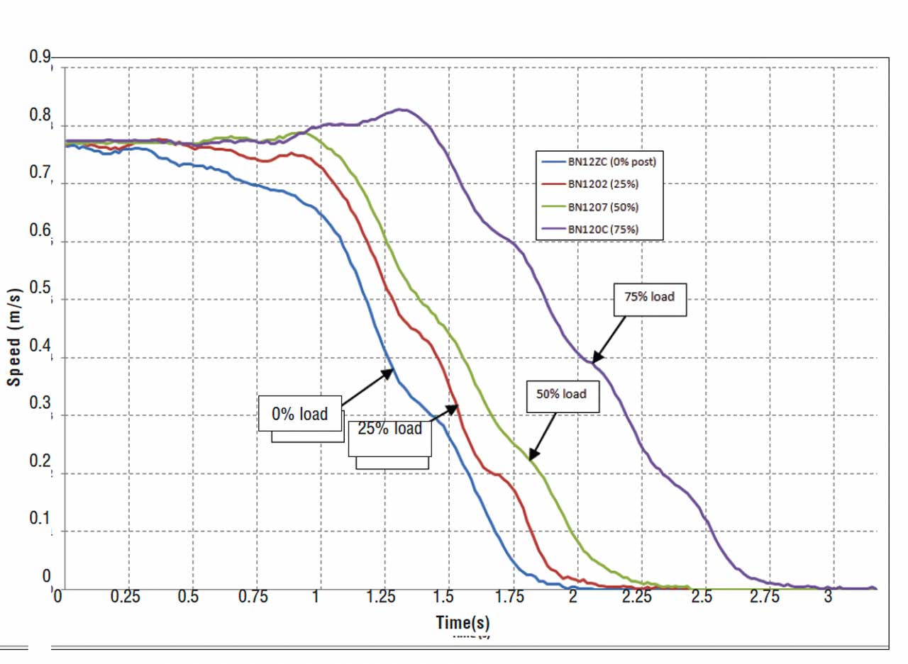
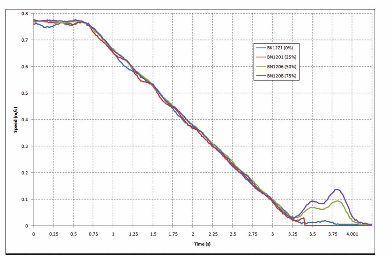
The speed time profiles captured by the use of the hand-held tacho-wheel provide a good overview of the advantages of the use of the electrically based braking compared to the conventional brakes. The hand-held tacho-wheel readings have the advantage that they provide time-referenced readings in relation to the initiation of a stop, although they are taken from the handrail rather than the step band (and thus provide lower accuracy). The variation against load of the stopping speed time profile can be clearly seen in Figure 8 for the auxiliary brake and in Figure 9 for the operational brake. However, as shown in Figure 10, there is very little variation in the speed time profile and stopping distance under different loading conditions when the escalator is stopped under the influence of the inverter. This is an excellent result and vindicates the use of the variable speed drive as the basis for the escalator intelligent braking system. The stopping distance under all load conditions is around 1100 mm.
It is, however, important to note that some slippage is occurring at the end of the inverter braking period at all loads, as shown in Figure 10. Some fine tuning is being carried out to eliminate this slippage.
The important result from the table is the low value of maximum deceleration with the electrically based intelligent braking (less than 0.5 m/s2). This is also an excellent result and shows the success of the electrically based intelligent braking system.
Types of Stops
As discussed in the previous sections, the system will resort to a conventional mechanical braking stop in case of failure of the electrically based braking system. For example, if the inverter receives an instruction to slow down and stop the escalator but fails to do so, the system will cause the mechanical brake(s) to apply.
The fact that the system might, in certain planned or unplanned cases, resort to the mechanical brakes to stop the escalator has necessitated the classification of the types of stops under which the escalator will stop. These are described below:
- Type I stop: The escalator is stopped under the influence of the inverter. This would be the expected type of stop under normal stopping conditions. This can also be considered a controlled type of stop.
- Type II stop: The escalator is stopped under the influence of the operational brake, with a delay applied to the application of the auxiliary brake. This stop will usually take place if the electrically based braking system fails.
- Type III stop: The escalator is stopped under the influence of both the operational brake and the auxiliary brake (without any delay). This stop will take place following the activation of certain types of safety devices (e.g., step-band over-speed).
Conclusions
Electrically based intelligent braking systems employ the variable speed drive to slow down the escalator and bring it to a standstill. The main benefit of intelligent braking systems is they can reduce or even eliminate the risk of passenger falls arising from unplanned stops. They also offer the potential benefit to differentiate in the stopping distance between different types of safety devices.
A system analysis and risk assessment has been carried out on a generic electrically based intelligent braking system. The system has been gradually enhanced to eliminate any potential single point failures. The final system has three lines of defense to protect against failures leading to a dangerous situation.
The requirements of EN 115:2008 have been assessed against the electrically based intelligent braking system to confirm that they do not prevent their use.
The final system has been tested on site. The results clearly show that the electrically based intelligent braking system is an ideal solution to address the variation in the stopping distance with load variations and the reduction of the risk of passenger falls. The system has been successful in eliminating variations between full load and no load, as well as reducing the maximum deceleration value during a lightly loaded stop to around 0.5 m/s2, which is well below the maximum allowable value of 1 m/s2.
The use of an inverter drive is fundamental to the implementation of electrically based intelligent braking systems. Where the inverter is already present within the control system, the incremental cost of implementing the electrically based intelligent braking system is by far outweighed by the safety benefits in terms of the reduction or elimination of the risk of passenger falls due to unplanned stops.
Acknowledgement
The authors acknowledge the contribution of the client for this project, London Underground Ltd., which supported this work, and to KONE Escalators UK, which supplied and installed the electrically based intelligent braking system.
Learning-Reinforcement Questions
Use the below learning-reinforcement questions to study for the Continuing Education Assessment Exam available online at Elevator Books or on p. 119 of this issue.
- What are the main problems of conventional braking systems?
- When a system resorts to the mechanical brakes to stop the escalator, what are the types of stops that have been classified?
- What are the two conflicting requirements a braking system must achieve?
- What are the two main categories under which the pass/fail criteria for any braking system will fall?
- What are the benefits of intelligent escalator braking systems?
References
[1] Lutfi Al-Sharif, “Asset Management of Public Service Escalators,” Elevator Technology 9, Proceeding of the International Conference on Elevator Technology (Elevcon ’98) Zurich, Switzerland, October 1998.
[2] BSI, “BS EN-115: 2008, Safety of Escalators and Moving Walks, Part 1: Construction and Installation.” 2008.
[3] Lutfi Al-Sharif, “Experimental Investigation into the Relationship between Passenger Comfort on a Stopping Escalator and the Kinematics of the Stop,” Proceedings of the 6th Jordanian International Mechanical Engineering Conference (JIMEC’6), 22 – 24 October 2007, Amman – Jordan.
[4] ASME, “ASME A17.1-1993: Safety code for elevators and escalators,” The American Society of Mechanical Engineers, 1993.
[5] Lutfi Al-Sharif, “Intelligent Braking Systems for Public Service Escalators,” Proceedings of the 1st International Conference Building Electrical Technology Professional Network (BETNET) Conference, BETNET 2004, October 2004, Hong Kong, China.
[6] CEN, “EN115, Safety rules for the construction and installation of escalators and passenger conveyors,” 1995.
[7] Wolfgang Stein & Reiner Ludwig “Brakes for escalators and moving walks,” Lift Report, Year 29, Issue 1/2003.
This continuing education article appears in Educational Focus, Volume 3, which can be found at Elevator Books
Get more of Elevator World. Sign up for our free e-newsletter.
![]()


![]()