Elevator Overspeed Governor Tripping-Speed Instrument Based on VI
Feb 1, 2013

by Yihui Ruan, Yucheng Qin, Baosheng Tang, Liang Ye, Haiten Liang, Zhe Cheng, Bin Zhao and Hua Pei
The overspeed governor is one of the most important safety components of an elevator system. The tripping speed of the elevator overspeed governor is one of its most important parameters. It includes both electrical and mechanical tripping speeds, and they are in chronological order. The parameters have a direct impact on lift safety, as lift-installation quality affects its normal operation to a large degree. The method this article introduces can accurately measure the two values in real time. The instrument makes the operation more convenient with a user interface.
Introduction
The tripping speed of the overspeed governor shall be checked in the direction corresponding to the descent of the car or counterweight/balancing weight. The operation of the stopping control shall be checked in both directions of movement, and tripping of the overspeed governor for the car safety gear shall occur at a speed at least equal to 115% of the rated speed and less than definite speed for different types of safety gears.
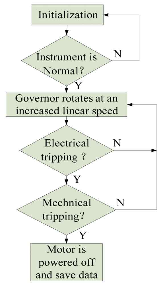
Virtual instruments (VIs) control a motor, the output shaft of which revolves the overspeed governor. The technical parameters (the elevator’s rated speed, diameter of the governor, etc.) can be set using a personal computer (PC) running VIs. Both the motor and governor have the same linear velocity. Once the governor is activated on the condition the electric safety device of the car safety gear mounted on the car is shorted, the values of the electrical tripping speed and mechanical tripping speed can be saved and displayed at once on the PC with the help of the LabVIEW program. Inspectors can then determine the conformity of the tripping speed with elevator standards.
Composition of Measurement
Figure 1 shows the hardware composition of the instrument. The system consists of a hall sensor, current sensor, servo motor, data-acquisition card and PC. The inspector can enter a value such as the elevator rated speed and diameter of the governor. The PC output signal is amplified and drives the servo motor, which makes the governor rotate.
The current sensor can detect whether there is current in the safety circuit. As the revolution speed of the governor is increased linearly, if the speed arrives at a certain value and the governor is activated, the safety circuit is disconnected. A signal that there is no current is transmitted to the PC via signal condition and data acquisition. The value of the electrical tripping speed is saved and displayed on the PC screen in real time. After the safety circuit is disconnected, the mechanical tripping of the governor occurs quickly. The hall sensor detects it and informs the PC instantly as the current sensor. The PC saves and displays this value. The pulses are generated by the hall and current sensors when the governor rotates. The signals from the sensors are amplified and filtered. “Data acquisition,” where signals that measure real-world physical conditions are sampled and converted into digital numeric values that can be manipulated by the computer, then takes place.
Software Design
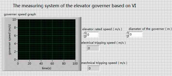
Figure 2 illustrates the measuring system of the elevator governor based on VIs created with the LabVIEW program using icons instead of conventional, text-based code. A VI consists of a front panel and a block diagram. The front panel (with knobs, switches, graphs, etc.) is the user interface. The block diagram, which is the executable code, consists of icons that operate on data connected by wires that convey data. Users can observe the changing and tripping speeds of the governor by means of the front panel (Figure 3). The algorithm is implemented by using the software. The measuring system of the elevator governor based on VI is characterized by simple structure, small volume, high response speed, low energy consumption and high reliability. In these ways and due to a user-friendly interface, the instrument makes the operation more convenient.
Get more of Elevator World. Sign up for our free e-newsletter.


