
FEA modeling of MRL elevator behavior under seismic conditions following EN 81-77
by Dr. Pascal Rebillard and Frédéric Grimault
Every year, at the worldwide level, the recorded number of earthquakes is between 500,000 and 1 million. Their consequences are, unfortunately, well known. People can be killed or greatly injured due to the collapse of buildings, and local economies suffer from the loss of business and reduced incomes from property damage and repair costs.
Based on historical data, Asia — and Japan, in particular — has been the continent most impacted by seismic hazards, although the U.S. is a highly seismic region, too. Notwithstanding, Europe should not be forgotten in the list of risky seismic regions. Most of its seismic activity is in its southern region (Greece, Italy, Romania, etc.), which is the most exposed to the effects of the African and Eurasian crustal plates’ confrontation. For example, in 2009, the Aquila earthquake in Italy killed 300 people and forced thousands to leave the region.
In Europe, seismology has continuously improved over time. It has made significant progress during the past 30 years thanks to sensors, electronics and computer technologies. These allow scientists to create better simulations and enhance prediction. Nevertheless, the 2011 nuclear accident in Fukushima, Japan, reminded European countries about potentially catastrophic consequences of an earthquake in countries with many nuclear plants, such as France.
An initiative launched in Europe in the 2000s created a code intended to help both elevator companies and architects take seismic effects into consideration. The standard is called EN 81-77: Safety Rules for the Construction and Installation of Lifts — Particular Applications for Passenger and Goods Lifts — Part 77: Lifts Subject to Seismic Conditions.
The demand for EN 81-77-compliant elevator systems is growing in Europe, even if this new code is still not well known by industry customers.
Starting with the “Horizontal Acceleration (ad)” category as defined in EN 81-77 Annex A, this technical paper presents an original finite element analysis (FEA) method enabling validation of the structural behavior of the elevator system in regards to seismic condition.
The energy generated by an earthquake is transmitted to the elevator by the building. All elevator components participate together to dissipate this energy. All the masses moving vertically in normal use in the hoistway (full cab weight and counterweight [CWT]) will apply important forces on the guide rails when submitted to horizontal acceleration. The integrity of the entire installation is then mainly guaranteed by the guide-rail brackets (GRBs) that sustain the cab and CWT guide rails. All interactions between major components (cab, CWT, guide rails and GRBs) and structural flexibility of each part of the elevator must be taken into account.
A complete numerical model enables analysis of the behavior of the guide rails and GRBs. This approach refines the results on the guide rails and GRBs in comparison with the one proposed by EN 81-77, in which the cab, CWT and GRBs are considered rigid (Figure 1). This is all the more important in a machine-room-less (MRL) elevator installation, because an important compression force is applied on each guide rail. In these installations, the whole system is sustained by the guide rails, because the machine and dead end hitches are fixed to the upper extremity of the guide rails. However, the car frame, CWT and machine bedplate are calculated separately, as if they participated to the energy dissipation individually. This choice was made for convergence considerations on the complete numerical model in which car frame and CWT are greatly simplified.
Currently, an FEA method is used to evaluate elevators’ structural behavior, mainly in vertical loads. The accelerations imposed on the structures are the gravity or speed variations in the vertical directions only. This applies as long as there are no other directions of stresses (caused by such events as earthquakes) for which the horizontal acceleration must then be considered in the design of the structures.
Depending on the severity of the seism, the magnitude of the horizontal acceleration (ad) can vary considerably. The value of this acceleration is the principal input to consider in the FEA analysis. Four seismic elevator categories depending on this acceleration value are given in EN 81-77.
Chapter 1: Calculation of Mechanical Subsystems
Car Frame
The cab is not considered a structural part. Only the car frame, which supports the cab (Figures 3-6), is calculated and analyzed. The heaviest cab of the range is considered, so an added concentrated mass representing the heaviest panels is included in the car frame model to have the correct cab mass and center of gravity.
Another added mass representing 40% of the maximum duty load is positioned 1 m above the floor, which is approximately the position of the human body’s center of gravity. All the masses of the model generate forces under the effect of the acceleration; thus, Von Mises stresses are calculated on all steel parts of the car frame. The forces in the links (bolts, rivets, welds and clinching points) are also analyzed.
Machine Bedplate
For an MRL elevator, the machine bedplate is fixed at the upper extremity of the guide rails (Figures 7 and 8). The last portion of the guide rails and the first level of the GRB just below the machine bedplate should be considered in the model, because their behavior will affect the machine bedplate. The machine affixed to the machine bedplate and the forces applied by the belts on the machine sheave are also implemented
CWT
The function of the CWT is to balance, as well as possible, the masses of the elevator installation (Figures 9 and 10). To achieve this function, the fillers must be maintained in the CWT, whatever the forces applied on the structural frame. In this kind of model, it is important to model all the fillers, because the horizontal seismic acceleration induces filler sliding and different magnitudes of forces applied by each filler on the uprights of the CWT. The precision on uprights stresses depends on these forces. The main risk is an escape of the fillers following the CWT frame
deformations. So, the stresses are analyzed not to exceed the yield stress of the steel for each part of the CWT. Only elastic deformations will then appear. Such deformations are not great enough to induce any filler escape.
Chapter 2: Calculation of the Entire Elevator Installation
The integrity of the whole elevator installation depends, among other things, on the guidance function. The GRBs, fixed to the hoistway wall, ensure the linearity and verticality of the guide rails. They also ensure suitable spacing between all the guide rails (for cab and CWT).
An important deformation of the guide rails (including GRBs) could induce an exhaust of the guide shoes relative to the guide rails. In this case, the guidance function would no longer be assured. So, control is essential to prevent the displacement of the guide rails under load from exceeding critical values that may compromise the guidance function. On the other hand, permanent deformations on the GRBs will affect the perfect linearity of the guide rails. The quality of the cab and CWT guidance will then be degraded.
All these requirements cannot be efficiently analyzed considering each component separately, so we decided to build a complete model (including GRBs, guide rails, cab and CWT) to take into account all interactions. In this model, the car frame and the CWT are simplified (all parts stuck together). They are only used to transmit the horizontal forces to the guiding system. This model is able to predict:
- Stresses on the GRBs
- Forces in the GRB links to the wall
- Deflection of the guide rails
- Displacements on each point of the installation
- Relative displacement between guide shoes and rails to evaluate the loss guidance risk

Figure 1 
Figure 2: Calculation process for our seismic validations 
Figure 3 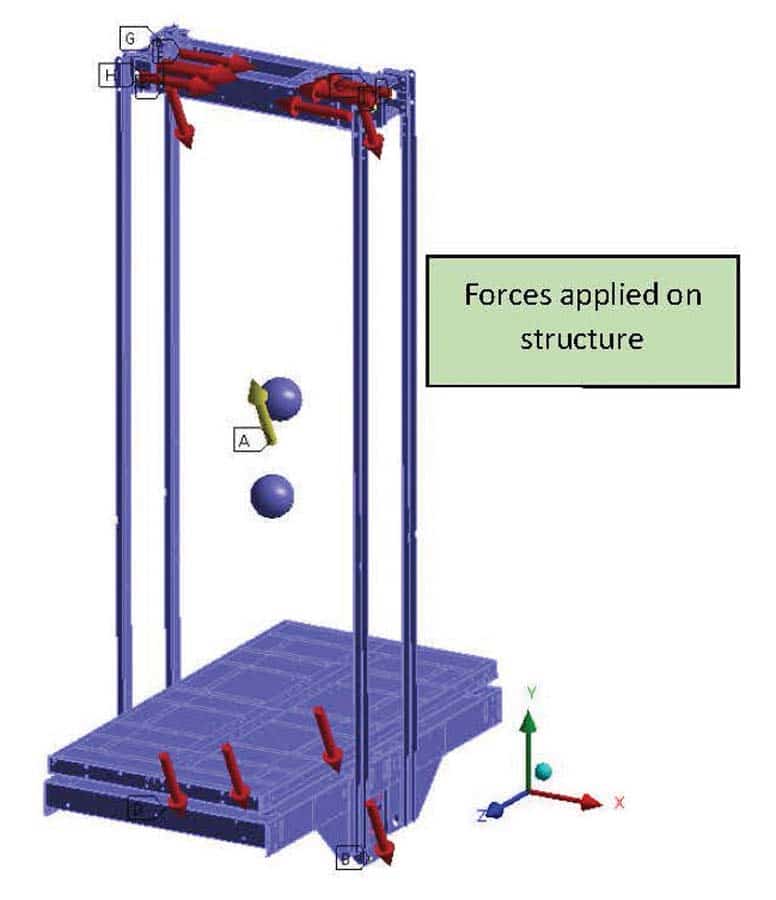
Figure 4 
Figure 5 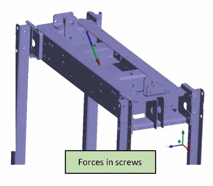
Figure 6 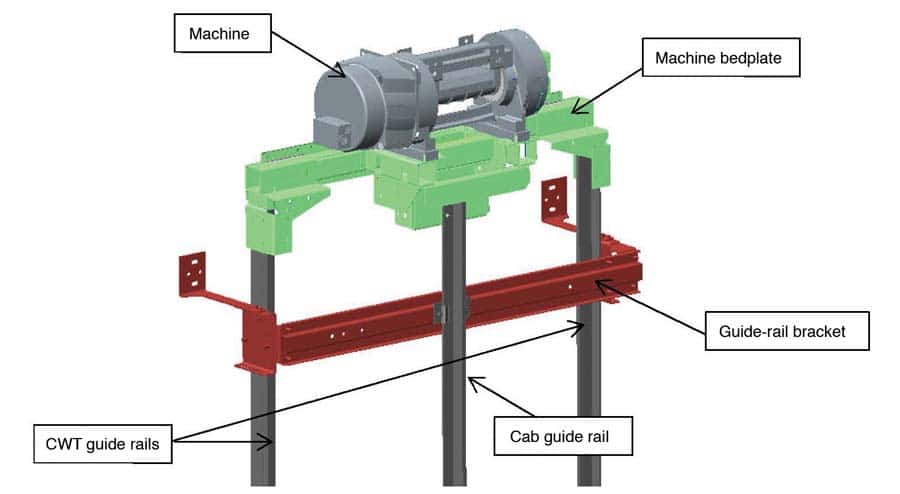
Figure 7 
Figure 8 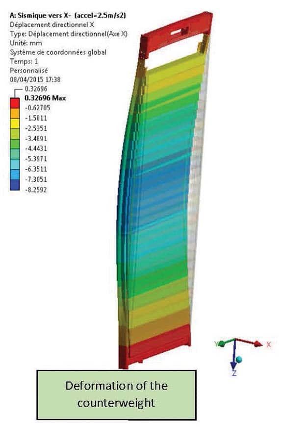
Figure 9 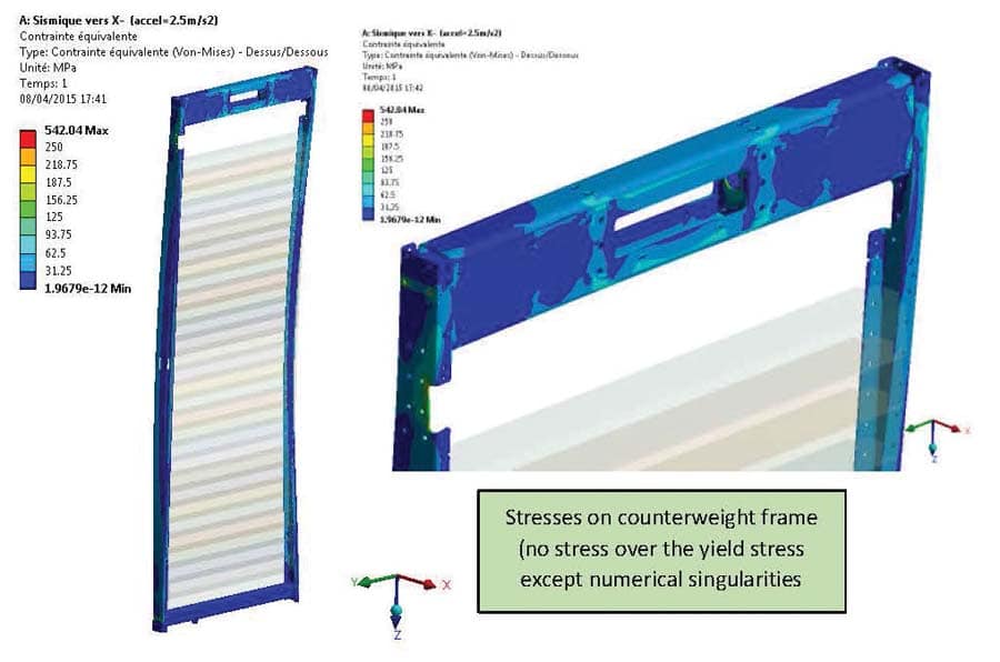
Figure 10 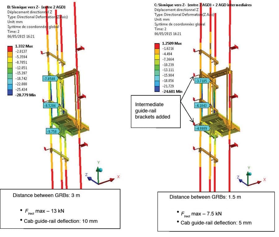
Figure 11: Deformations under seismic load 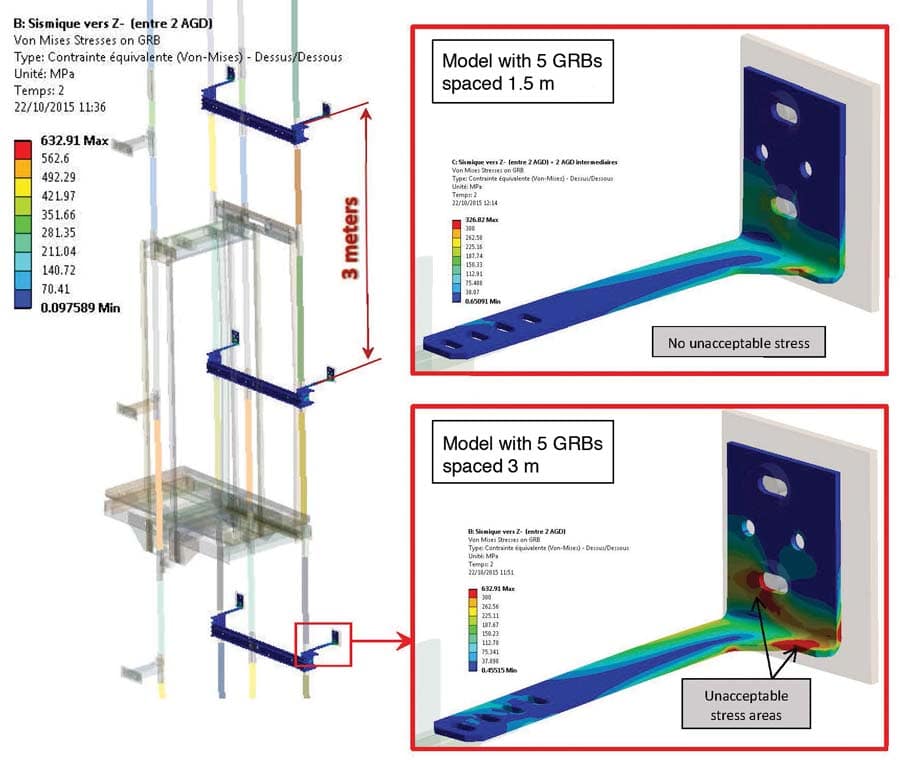
Figure 12: Stresses under seismic load 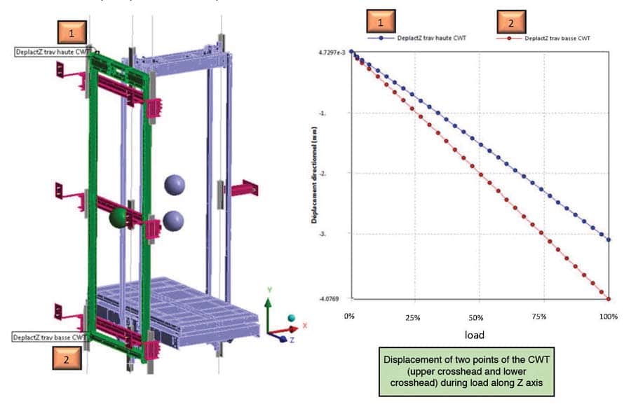
Figure 13 
Figure 14
Analysis Example
In the following example and Figure 11, a first analysis with one GRB every 3 m in the hoistway showed that a 2.5-m.s-2 seismic acceleration induced three problems when the cab guide shoes are located between two GRBs:
- Traction forces in the GRB links to the wall over their acceptable limit
- Deflection of one cab guide rail over 5 mm (maximum value allowed)
- Von Mises stresses that exceed the yield stress in the GRBs
The solution is to add intermediate GRBs (at least one every 1.5 m, instead of every 3 m). The numerical results are shown in Figures 11 and 12.
Finally, with GRBs spaced 1.5 m instead of 3 m:
- The traction forces in the links to the wall became acceptable
- The guide rails’ deflection was divided by two
- The stresses in the GRBs became acceptable
As this shows, it is necessary to keep the configuration with GRBs spaced 1.5 m apart and to reinforce them to keep a correct factor of safety. The CWT guide rail deflection is approximately 4 mm near the lower crosshead of the CWT (Figure 13).
The guidance behavior is acceptable, even with GRBs spaced 3 m. Indeed, we can see that the relative displacement between the lower cab guide shoe and cab guide rail is approximately 11.5 mm (Figure 14), but the nominal overlap of the cab guide shoe on the cab guide rail is 28 mm, so it remains an overlap of 16.5 mm, despite the seismic deformation.
Conclusion
An FEA method used to validate the structural behavior of the elevator system in regards to seismic conditions indicated in EN 81-77 has been described. The benefit of this original method is to predict the seismic behavior of the complete elevator system, taking into account the mechanical interactions between the main subsystems (cab, CWT, GRBs and guide rails).

Dr. Pascal Rebillard is manager of the Systems Analysis & Modeling department at Otis and a fellow for Elevator Systems supporting Otis development teams around the world. He joined Otis in 1991 and started his career in Gien, France, as a research engineer charged with creating an acoustics laboratory and addressing all noise- and vibration-related matters. At the same time, as part of a mission in the FAIS (French federation of the elevator companies), he worked closely with the French Ministry of Housing and led a Working Group to define new elevator acoustic regulations now in place in France. He also acted as a project manager during the development of the Otis Gen2® product range. Rebillard holds a doctorate in Physics from the University of Maine in Le Mans, France.

Frédéric Grimault has been in charge of numerical validations of elevator structures in the Finite Element Analysis & Modeling department at Otis’ Gien, France, R&D center since 2007. Grimault began his career in the automotive industry. He received his Engineering degree from Institut National des Sciences Appliquées in Lyon, France, in 1993.
Get more of Elevator World. Sign up for our free e-newsletter.


