An examination and case study of safety-focused escalator enclosure design
All mechanically moving parts of the escalator or moving walk should be completely enclosed within imperforate panels or walls.
Exempt from this are the accessible steps, accessible pallets, accessible belt and handrail section available to the user. Many escalator manufacturers use stainless-steel sheets as an enclosure device, so stainless-steel thickness and design play a big role in cost of production. In this article, various designs with different thicknesses will be considered in accordance with Kirchhoff-Love plate bending theory and finite-element-method (FEM) analysis with ABAQUS/CAE 2018.
Allowable value and design measurements have been defined by BS EN 115-1:2017. Plate boundary condition is assumed to equal the fully clamped and governing equation derived by the Ritz method, also called the “energy method.”
Introduction
Cladding is a major part of the escalator that is used for three purposes:
- Preventing access to moving parts inside the escalator[1]
- Protecting devices within the escalator from wind, rain, dust and other adverse environmental conditions
- Improving the appearance and making the entire design of the escalator more attractive[2]
Cladding is used in public-transit escalators. It is largely made of stainless steel in two parts as side cladding for the side enclosure and soffit (enclosure under the truss). Material and thickness play important roles in the cost of public projects. This is why a highly appropriate design brings down costs in a many units.
In 1850, Gustav Kirchhoff published an important thesis on the theory of thin plates. In this thesis, Kirchhoff stated two independent basic assumptions that are now widely accepted in the plate-bending theory and are known as Kirchhoff ’s hypothesis.[3] Transverse stress and strain components are ignored in classical or thin-shell theories. A rigorous plate theory that considers the deformations caused by the transverse shear forces was introduced by Reissner. In 1956, M.J. Turner, R.W. Clough, H.C. Martin and L.J. Topp introduced the FEM, which permits the numerical solution of complex plate and shell problems in an economical way.[4] In 2013, J.L. Mantari and his colleagues introduced finite-element formulation of a generalized higher-order shear deformation theory for advanced composite plates.[5]
Consider a square plate made of stainless steel, applying the Ritz method to plate bending.[4] The strain energy, U, associated with plate bending is:

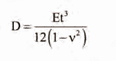
where D is flexural rigidity.
In the present work, we assume that the elasticity modulus, E, and plate thickness, t, are described by Eq. (2), while Poisson’s ratio, v, is considered constant across the thickness. The work done by the lateral surface loading, p(x, y) is represented as:
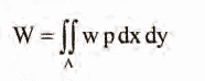
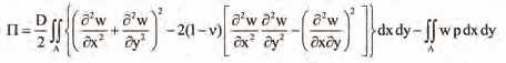
where A is the area of the plate surface. Therefore, the potential
energy π = U – W is:
The application of this method is illustrated by considering the bending of a built-in edge (fully clamped) square plate carrying load p. The boundary conditions are:
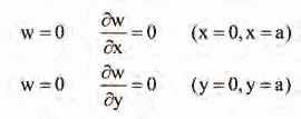
Integration by parts of the last term in Eq. (1) and according to above boundary condition equations, it becomes:

Therefore, the bending strain energy is reduced to:

Assuming a deflection expression of the following form:

the boundary conditions equations are satisfied. A load, P, is then applied at a location

in which there is maximum deflection of the plate. From the minimizing conditions

it follows that:

By obtaining the values

in which

the maximum deflection occurring at the center of the plate, is found to be:

Analytical and FEM Solution
Analytical and FEM solution are compared here for a square plate with a condition as detailed in Table 1.
| Parameter | Unit | Value |
| Density | kg/m3 | 7900 |
| Elastic Modulus | Gpa | 193 |
| Poissons Ratio | 0.275 | |
| Min. Yield Strength | Mpa | 205 |
| Square Plate Dimension | mm | 941 X 941 |
| Flexural Rigidity (D) | Gpa | 61.76 |
| Plate Thickness | mm | 1.5 |
Assuming a concentrated load in the center of the plate by introduction of Table 1’s data into Eq. (10) and FEM analysis by ABAQUS/CAE 2018, it results in Table 2.
| Parameter | Unit | Analytical | FEM |
| Max Deflection | mm | 19.5 | 21 |
| Percent Error (%) | 7 |
Shell elements have been assigned to the plate, and the deflection is shown under concentrated load P = 250 N as it is mentioned in EN 115.[1] The 7% error is due to the result obtained by taking only seven terms of the series. The more terms in the calculation, the more accurate the result will be.
Load type, which is described in EN 115 as applying load for cladding, is patch load that should act on a specified area. The exterior panels shall withstand a force of 250 N at any point at right angles on a round or square area of 250 mm2 without breakage.[1] Here, the yield stress point is suggested as a critical point in design criteria. That is why permanent deformation will occur beyond the elastic limit. The elastic limit is the lowest stress point at which permanent deformation can be measured. This investigation leads to a safer situation in design, and the real safety factor will be greater. In Table 3, patch load results are demonstrated against concentrated load at the panel center. The deflection value at the panel center is relatively the same in each, but tension in the patch load is considerably decreased.
| Parameter | Unit | Point Load | Patch Load |
| Max Deflection | mm | 21 | 20.6 |
| Max Tension | Mpa | 264 | 171 |
| Safety Factor | 0.78 | 1.2 |
Case Study Result
Two panels in the middle and upper parts of the escalator are considered here. These particular panels are installed in the Shiraz, Iran, metro stations. Thickness is an important dimension by which to define the safety factor. Panel height in the middle and upper parts are 1,817 mm and 2,933 mm, respectively. The width of the middle panel is 941 mm, and it is larger than the upper panel. Recommended minimum plate thickness in technical documents for a public project in Asia is 1.5-mm 304 stainless steel grade.[7-9] Despite the fact that this material type and thickness are suitable in cladding design, the North American standard specifies thickness should be more than 2 mm 316 stainless steel that is quite resistant to corrosion.[10] In commercial escalators, panels are designed with stringers in which thickness is 1-1.5 mm.
Deflection, tension and safety factor will be considered as in Figure 3. This line chart describes that, while thickness is increasing, deflection in the panel center is decreasing markedly. Although the upper panel is taller than the middle one, its deflection is lower. The descending value in the chart is like that of an exponential function. The maximum deflection location is shown in the upper and middle panels. Maximum tension occurs at the panel center in which patch load is applied on a square area.
Figure 5 represents an ascending exponential function showing that 1.5-mm thickness is acceptable for cladding design in this situation (in accordance with the plate dimensions and materials). 1.2-mm plate thickness is not acceptable for cladding manufacturing due to the safety factor value.
Conclusion
According to EN 115 design criteria, minimum acceptable thickness in public projects in which high-dimension panels are used is 1.5 mm. Panel width is an important dimension in reducing deflection value. Patch-load tension is less than point-load tension, but deflection is the same. To create a better design, stringer-equipped panels are suggested to obtain a higher safety factor with a lower cost of manufacturing due to less thickness. Boundary condition types must be fully clamped on all edges to fulfill requirements such as tension and a maximum 4-mm deflection to avoid creating a gap.[1] All edges can be bent to provide a clamped boundary condition with supports for fixing.
-
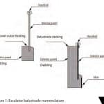
- Figure 1: Escalator balustrade nomenclature
-
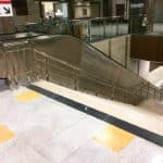
- Figure 2: Escalator side cladding in the Shiraz, Iran, metro
-

- Figure 2: Escalator side cladding in the Shiraz, Iran, metro
-
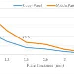
- Figure 3: Plate deflection compared with thickness
-
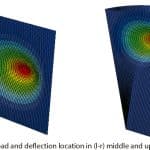
- Figure 4: Load and deflection location in (l-r) middle and upper panels
-
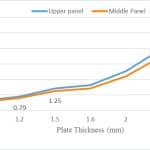
- Figure 5: Tension safety factor compared with thickness
References
[1] British Standards Institution (BSI). BS EN 115-1:2017: Safety of Escalators and Moving Walks – Part 1: Construction and Installation, BSI: 2017.
[2] IRSA MEHR. Escalator Cladding Catalog, first edition. Iran: 2017.
[3] Eduard Ventsel and Theodor Krauthammer. Thin Plates and Shells Theory, Analysis and Application. Marcel Dekker, Inc.: 2001.
[4] Ancel C. Ugural. Stresses in Plates and Shells. second edition. The McGraw-Hill Cos.: 1999.
[5] J.L. Mantari and C. Guedes Soares. “Finite Element Formulation of a Generalized Higher Order Shear Deformation Theory for Advanced Composite Plates,” Composite Structures, Vol. 96 (2013), p. 545–553.
[6] ATLAS STEELS. “Stainless Steels Grade Datasheets” (atlassteels.com.au).
[7] Shiraz Metro Line 1. “Escalator Technical Specification”: 2016.
[8] India Metro. “Escalator Technical Specification”: 2014.
[9] Suzhou metro. “Escalator Technical Specification”: 2015.
[10] American Public Transportation Association. APTA RT-EE-RP-001-02: Heavy-Duty Transportation System Escalator Design Guidelines: 2011.

Get more of Elevator World. Sign up for our free e-newsletter.
![]()


![]()