Give Me a Brake
Feb 1, 2019

The purpose, solutions, servicing and design considerations of the safety brake
The elevator safety brake has come a long way since the mid 19th century when Elisha Graves Otis first demonstrated his safety brake that would revolutionize the industry. It is fair to say the elevator didn’t gain popularity until the safety brake was developed. Modern elevators now use a variety of different safety braking technologies, depending on usage and design criteria. The general principle remains the same: provide reliable protection of passengers, cargo and equipment. This article will look into the purpose, the solutions and how they work, servicing, and design considerations.
Elevator and hoist designs around the world share one common feature: the safety brake. The brake is a motion-control device. It prevents unintended movement, holds in place and sometimes prevents overspeed conditions. It is also used for emergency stopping, like in a power outage or momentary power loss. There are several types of brakes in the industry today. They can be actuated electrically, hydraulically or mechanically. Many are electrically actuated, so we will focus primarily on them.
Brakes are generally designed per the torque requirement. A heavy load requires more holding torque. Torque is equivalent to a force acting at a distance, normally referenced in feet pounds- force (ft..lbf ) or Newton meter (N.m). We can calculate torque from a simple equation related to horsepower and rpm. Torque (ft..lbf ) = 5,252 * horsepower * service factor/rpm. Another important consideration in brake selection is inertia for dynamic braking or emergency braking when the load is in motion. We can calculate the torque required to decelerate a load when the inertia value is known. Torque (ft..lbf ) = (inertia * the change in rpm)/(308 * the time required to stop). wk2 represents reflected inertia, which can also be written as T = wk2 * ∆ rpm/308t.
Dynamic braking can require a brake to absorb a large amount of energy. “Energy absorption” usually means heat and wear of the friction surfaces. Energy is equivalent to inertia multiplied by the speed squared. Holding brakes are mostly designed with a high coefficient of friction material for the mating (friction) surfaces.
Although the material in a holding brake has a high torque capacity, the downside is that it can wear quickly during dynamic braking. So, the brakes are generally rated for a certain number of test or emergency stops; more accurately stated, they are rated to absorb a certain amount of energy over time. E = (1/2)mv2 can be broken down into the following energy equation:
Ee = (M * v2 * td)/[k *(td + tl)] (Equation 1)
where Ee = energy per engagement; M = inertia; v = speed; td = dynamic torque; tl=load torque; and k is a constant.
There are other types of brakes designed for dynamic stopping altogether. Those have a special friction material that limits the amount of wear on the friction surfaces (reduces the wear rate). The dynamic-stopping friction material still maintains a reliable torque-carrying capacity. Over time, you will notice that dynamic stopping will cause wear, and that wear will be evidenced in a larger air gap between the friction surfaces. That is why we sometimes need to adjust the airgap on adjustable brakes. From Equation 1, we can use the energy per engagement and put that into the lifecycle formula:
L = v/Ee*w (Equation 2)
where L = life in cycles; v = total engagement area; and w = wear rate.
Electromagnetic Brakes
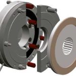
Electromagnetic brakes function with built-in airgaps that prevent rubbing/braking when the machine is to be in motion. An exploded view of a simple power-off electromagnetic brake is in Figure 1. measured with feeler gauges when the brake is engaged (powered off ). To measure the airgap between the friction surfaces, disengage the brake either by applying power or with a manual release mechanism. Obviously, special precautions shall be made when disengaging a safety feature during maintenance. Th e airgap is an important feature of a brake, because the magnetic fl ux needs to travel across that airgap distance to magnetically pull the pressure plate in. If that gap is too large, the magnetic force will not overcome the force of the coil springs. Ideally, the airgap will be as small as possible without allowing the components to rub together. Each manufacturer provides the recommended airgap for each product. Smaller brakes typically have smaller airgaps.
In basic operation of a power-off electromagnetic brake, the coil is naturally deenergized (no power being applied). Th ere are coil springs inside the brake that apply normal force to push the pressure plate against the friction disc and clamp it against the rigid cover plate. Th e friction disc is connected to a hub in the brake, which is mechanically fastened to a shaft , holding that shaft in place. To release the brake, apply power (current) to the coil. Th at coil then works as an electromagnet to pull the pressure plate away from the friction material. Th e movement of the pressure plate compresses the coil springs; then, the pressure plate is magnetically locked to the field coil, and the shaft is then free to rotate. There are several variations of power-off brakes, but this is the basic concept.
Although this type of brake is applied without power, it needs electric current for its release. The coil springs are compressed as the magnetic flux pulls the pressure plate toward and against the field coil. It takes more energy to pull in the pressure plate and compress the springs than it does to simply keep the pressure plate clamped to the coil and the brake disengaged. For that matter, a power controller can provide a quick burst of power, called “overexcitation,” for a very short time, while the brake disengages. Once the brake is disengaged, the power controller can drop the power through pulse-width modulation to keep the brake disengaged. This essentially reduces the total power consumed by the brake and makes it more energy efficient.
Spring-Applied Brakes
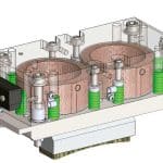
Spring-applied brakes for the elevator industry often have special design features, compared to general industrial brakes. These features focus on safety, reliability, serviceability and low noise. An example is a double-brake design that features two brakes stacked together for redundancy (Figure 3). It is used on mini-machine-room (MMR), machine-room-less (MRL) and home elevators.
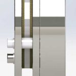
There are also other designs, including the single-disc design with two half-moon armatures (Figure 4). For tight spaces, this thin-profile, low-cost brake provides high torque stability, low noise and a manual release option. It is used on MMR and MRL elevators.
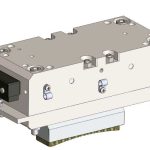
A spring-applied caliper brake (Figure 5) works in the same fashion. Springs apply normal force to mechanically engage the brake. The brake is disengaged by applying electric current to the coil. In the case of hydraulic spring-applied brakes, applying hydraulic pressure, instead, releases the brake. For either type of caliper-style brake, extra reliability or safety factors can be built into the system by adding multiple caliper brakes on a single disc. Caliper-style brakes are able to offer high torque versus cost, because the holding force is acting on a large disc radius. Torque = force * distance (radius).
Drum Brakes
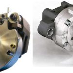
The drum brake (Figures 6-9) is yet another type of brake. Unlike the rotary-spring-applied brakes mounted on the back side of a motor or the caliper brakes mounted on the large drum disc, these brakes can be mounted to directly apply braking force to the drum itself. One type, an expanding-type brake, mounts inside the drum. The drum interior diameter is the brake’s friction surface. For extra safety and reliability, multiple brakes can be mounted inside the drum. It operates much like the other spring-applied brakes in that the holding force is achieved through spring force, and it is actuated (released) electrically.
If room is not available inside the drum or for other reasons, an external-band-type drum brake can be used. In this case, the drum’s outside diameter is the friction surface. The brake carries a thin profile, facilitating easy removal for maintenance. Manual release options are available, and multiple brakes can be used on a single drum for added safety and reliability. Like a caliper brake, the force exerted on a large radius can provide a high level of braking torque.
Hydraulic Brakes
Prior to 1972, all hydraulic elevators were installed without a cylinder safety device. A few accidents over the 50 years prior related to single-bulkhead failures caused some codes to be rewritten. Electrolysis is known to be the main source of damage to cylinders and other critical underground components in the hydraulic system. Double-bulkhead cylinders or another car safety feature could be used to provide an extra safety factor. The LifeJacket® system by Adams Elevator Equipment Co. (Figures 10 and 11) is a popular solution on its own. It is the only plunger- gripper-style safety device to prevent an elevator from undesired downward movement. If there is loss of hydraulic pressure or uncontrolled downward movement, it actuates and grips the plunger to bring the elevator to a controlled stop. When pressure drops in the control cylinder, the plunger gripper sets. This is achieved either by energizing the LifeJacket set valves, or hydromechanically due to a pressure drop in the elevator system. Two control valves provide redundancy for secure operation.
Maintenance and Troubleshooting
Reasons why brakes might not operate as intended include oil or grease, which should be kept away from them at all costs. Contamination of the friction surfaces will greatly reduce the brake torque. Water and ice should also be kept away from the brake. Some friction materials are hampered more than others by moisture, but it is generally not good for a brake. Dust can also be an issue if it gets on the friction surfaces, so brake covers or dust straps may be needed to prevent its entry. Proper power also needs to be applied to a brake: too much can overheat it, and too little may cause it not to release. While it is possible for a brake’s coil to become damaged, the more-likely suspect is improper connections, damaged wires, incorrect wire sizing or an intermittent power loss. The manufacturer’s recommendations should be followed.
If noise is an issue, check for contamination, and check the airgaps. Check the alignment, if appropriate for that brake type. You can also check for any heat marks or wear on the brake. Lastly, if service has recently been performed, make sure that the manual release is not activated on the brake. This would cause it to be permanently disengaged.
-

- Figure 1: An exploded view of a simple power-off electromagnetic brake
-
- Figure 2 shows how an airgap can be
-
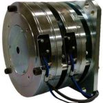
- Figure 3: An Ogura MWB-WB or RNB-WB double brake that off ers a small outside diameter, high torque stability and manual release option produces noise less than 60 dBA.
-
- Figure 4: Ogura’s MNB-W series, a single-disc design with two half-moon armatures
-
- Figure 5: Two caliper-style ENB-CP Series spring-applied brakes from Ogura
-

- Figure 6: A drum brake
-

- Figure 7: Sketch of an Ogura ODNB-series drum brake
-
- Figure 8: Cutaway of an Ogura ODNB-series drum brake
-
- Figure 9: Full rendering of an Ogura ODNB-series drum brake
-

- Figure 10
-
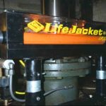
- Figure 11
Get more of Elevator World. Sign up for our free e-newsletter.


