The importance of protecting against heat and using thermal imaging instruments in elevator systems
by David Herres
Elevators are complex assemblies of electrical and mechanical components. These components produce heat, usually due to electrical resistance or mechanical friction. Excess heat is dissipated into the adjacent space if not removed by means of active cooling. Equilibrium is usually maintained, but if excessive heat is generated or if the cooling method is compromised, temperature rise occurs in the electrical or mechanical components, and there is a high probability of shortened life or even immediate failure.
Shortened component life and failures are potentially grave for elevators, because human injury and equipment outages cannot be tolerated. Excessive temperature sometimes rises to a certain level and finds a new equilibrium. Or, it can increase and cause irreversible damage, resulting in equipment failure and/or catastrophic fire. Electric motors often run without incident for years until high ambient temperature, overloading or manufacturing or installation flaws, seemingly without warning, can set the stage for excess heat, which can damage electrical insulation within the motor, cause it to draw excess current and result in still more heat and eventual failure.
| Learning Objectives |
| After reading this article, you should have learned about: ♦ Heat as it relates to electrical faults ♦ Causes of temperature rise in electric motors ♦ Instruments for measuring heat ♦ Thermal imaging instruments ♦ How to use the Fluke PTi120 |
Of course, there are safeguards. Overcurrent devices such as circuit breakers and fuses and, in larger motors, heat sensors embedded in the windings, should shut the system down before there is extensive damage. Sprinkler systems, chemical fire suppression and fire alarms are effective, but they may be missing or not fully functional in older buildings. This is where maintenance workers play a key role. Typically, they make the rounds each shift, checking equipment throughout the facility. In an elevator machine room (or at the motion controller in machine-room-less installations), an inspection sheet should be posted with relevant measurements, time, date and workers’ initials. The information contained in this log is invaluable in detecting and evaluating damaging trends, and it is helpful in diagnosis and repair. The object is to spot damaging trends earlier, rather than later. This requires measuring instruments.
Various means for measuring temperatures are useful in an elevator machine room, where the motor, motion controller and electrical disconnect are located. A wall thermometer (standalone or part of a heating or cooling thermostat) provides a reasonably accurate and convenient way of ascertaining the ambient temperature. This metric is important as a first step. A machine room is normally cooled by one or more fans, which, of course, must be vented to the outside. Sometimes, depending on the climate, size of the machine room, number and size of the motor(s), and other factors, an individual room air-conditioner or central air vent is installed. Either of these can fail and needs to be monitored. Individual heat sources can also be measured. Separate thermometers can be affixed to the motor(s): one at each end at the bearings and one at the center to measure heat from the windings.
Electric motors often run without incident for years until high ambient temperature, overloading or manufacturing or installation flaws, seemingly without warning, set the stage for excess heat, which can damage electrical insulation within the motor, cause it to draw excess current and result in still more heat and eventual failure.
The motor controller and any large transformers or switchgear can be equipped with heat sensors with digital readouts attached to the outside of the enclosures. A small stick-on analog thermometer is appropriate for the outside of the gearbox used in geared traction elevator motor drives. For hydraulic elevators, this location is the outside of the oil reservoir. Any of the sensing devices can be wired or connected wirelessly to a red warning lamp above the door just outside the machine room.
Most modern elevators are driven by powerful three-phase electric motors, which draw a substantial amount of current. Current-carrying conductors enter the machine room and terminate at the disconnect, variable-frequency drive input and output and motor terminals. In the initial installation, these terminations are precisely torqued according to specifications based on size, the type of metal (copper or aluminum) and, ultimately, the motor rating (in amperes). If they are too tight, the threads may be damaged, and, in time, they will loosen. If they are too loose, they will overheat or arc under a heavy load, creating great heat and corrosion. Running on reduced voltage or a dropped phase, motor windings become heat elements and present the possibility of an electrical fire.
In addition to the motor, other electrical devices produce heat as a natural byproduct of their intended function. A resistor connected in series between the power source and load causes a reduction of current in the circuit, and the excess energy is dissipated by the resistor in the form of heat. Semiconductors, as discrete components or imbedded in integrated circuits (ICs) also dissipate heat. They all have in common the fact that too much heat will rapidly destroy them. A component may appear charred or physically distorted, but it often functions as an overcurrent device, opening the circuit before visible damage occurs.
Faulty wiring and cold solder joints introduce unwanted resistance, hotspots and excessive heat dissipation in circuit boards, the cabling that connects them and the wiring from the power supply. This heat can damage small surface-mounted components, particularly ICs. Electrolytic capacitors, used where high capacitance is required, sometimes fail. High capacitance in a relatively small package is achieved by means of a very thin electrolytic layer. This is an electrochemical product formed the first time voltage is applied. Its downside is that it is prone to aging, and the electrolytic layer is easily damaged. When this happens, there is a parallel resistance and abnormal heat dissipation.
An elevator motion controller typically contains several printed circuit boards, each with many active and inactive components. Many technicians touch each component to estimate the temperature. A component that is excessively hot probably has an internal short, and if it is cold, the short has resolved into an open. However, it is possible that it is temporarily out of the circuit, that the supply of power is not getting into the component or that the ground return has lost continuity. The latest complementary metal oxide semiconductor devices operate at a lower voltage and do not dissipate a perceptible amount of heat.
Estimating heat dissipation by touch has the disadvantage that you can inadvertently contact an energized surface. While most circuit-board components operate at low, intrinsically safe voltages, it is always possible that an external fault is applying a higher voltage to the component, creating a hazardous situation. A good solution is to use an electrically insulated temperature probe and a multimeter designed for the purpose. The digital readout will display the exact temperature in Celsius or Fahrenheit degrees.
Heat management is critical in this age of electronic miniaturization, where large numbers (often millions) of components are etched on small silicon substrates and assembled as ICs. Discrete components are often intentionally undersized; to compensate, finned heatsinks are attached to extract excess heat.
Components and circuit boards should be located with efficient heat distribution in mind. As long as there is not abnormally high ambient temperature or dust accumulation on the outside of the enclosure or a malfunction of a cooling fan, the device remains functional.
The most advanced tool for finding hotspots is the thermal imager, which shows an infrared picture of the device under investigation in real time. Alternatively, it can create and display a digital photograph that can be downloaded in JPEG format, where it can be saved and analyzed, printed or emailed.
Thermal imagers have been around for a long time, but recent models have new, advanced features with great capabilities. They make outstanding maintenance and diagnostic tools. Elevator technicians can quickly image all drive motors, variable-frequency drives, sheaves and bearings, motion-controller circuit boards, electrical terminations, door mechanisms, hydraulic reservoirs, and other electrical and mechanical components. Hotspots are immediately evident, often before serious damage occurs.
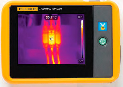
Fluke manufactures several thermal imager models, greatly ranging in price. A good choice for elevator preventive maintenance and diagnosis is the Fluke PTi120 9-Hz Pocket Thermal Imager. Unlike other models, this instrument is compact enough to fit in a shirt pocket, yet durable and
well-sealed from contamination and moisture. The user can view infrared images in real time, or, in the camera mode, these images can be saved in the instrument’s memory. Moreover, using the included USB cord and free software, infrared images can be saved as JPEG files.
The PTi120 has a 3.5-in. LCD touchscreen. Its many functions and extensive menus can be easily accessed by tapping on the screen. To capture an accurate and readable thermal image, after turning it on, the instrument must be allowed to warm up for 3-5 min. Continue for a minimum of 10 min if accurate measurements are essential to your application.
A surprising feature is that the imager also functions as a conventional visible-light digital camera. Fluke calls this combination IR-Fusion. If the user draws their finger across the touchscreen from right to left, the infrared image morphs inContinto a ued visible-light image, the two modes blending progressively as the finger progresses. The imager self-calibrates from -4 to +302°F (-20 to +150°C). A meaningful image will be produced, regardless of whether the user is looking for slight temperature variations on a circuit board or a motor heating to well over the boiling point of water.
A vertical bar at the right of the screen shows the range of colors that comprise the current image. By default, white and orange represent the hot end of the temperature spectrum; black and blue represent the cold end. Above and below this color bar are maximum and minimum temperatures in the current image. At the top-center is the temperature at the center of the display, marked by a crosshair icon. The user can aim the camera for a targeted temperature reading.
The horizontal menu bar appears at the top with a single tap on the screen. Here, there are six menu items represented by small icons. From left to right, they are:
- “Memory,” which permits the user to add a note to multiple images
- “IR-Fusion,” which displays a bar showing the percent of thermal versus visible light in the image
- “Palette,” which permits the user to alter the colors used to represent various temperatures: there are alternate color schemes, with the current one indicated.
- Temperature indicators, which can be toggled on and off: “Spot Temperature,” “Center Point,” “Scale” and “Status Bar”
- “Torch,” which controls the built-in LED spotlight
- “Settings,” including “Scan Asset ID,” which permits the user to scan an object’s barcode; “Fluke Connect,” which permits the user to save images to the Fluke Connect Cloud; “Pair Hotspot to Fluke Connect”; “Save Images to Shared Folder”; “IR Settings”; “Emissivity, Background Temperature and Transmissivity” in percentage; and “Device Settings,” permitting the user to toggle file formats (IS2 or JPEG), set units, time, date and language, and “Reset the Imager” to factory defaults.
Heat management is critical in this age of electronic miniaturization, where large numbers (often millions) of components are etched on small silicon substrates and assembled as ICs.
the object, the instrument probably hasn’t warmed up sufficiently or is being held in such a way that its lens is blocked. For the best thermal image, “IR-Fusion” should be activated by sliding a finger about one-quarter way across the screen (providing an image with approximately 25% visible light).
Since infrared radiation is emitted by all objects with a temperature above absolute zero, daylight is not required to capture a thermographic image. This is in accordance with the black body radiation law. Black body radiation varies with the frequency that relates to the temperature of the body, making thermal imaging possible. A varicolored image corresponding to its temperature map may be seen in real time or captured digitally because different areas of the surface of the object or landscape are at different temperatures. This map is very useful in the analysis of a working machine.
The intensity of black body radiation varies with temperature. It may be less than expected for a given body due to the concept of emissivity, which is the ratio of actual radiance to theoretical black body radiance. By definition, emissivity is between 0 and 1. A black body is only truly black when its emissivity is 1, and it absorbs all the radiation that strikes it. Radiation includes higher-frequency components outside the visual spectrum, such as X-rays. Emissivity is a product not solely of the body, but of the interface between it and the adjacent material, usually a gas.
The thermal imager self-calibrates based on the emissivity of the surface being measured. Tapping the PTi120’s thermal imager screen once displays the main menu; then, tapping the gear icon displays “Settings.” Here, the third menu item is “IR Settings.” At the top is emissivity, with a note that electrical tape is 0.95. What this means is that if a short length of black electrical tape is stuck on an object to be imaged, the color as seen in the imager screen will correspond to an emissivity of 0.95. Sometimes, black tape is not feasible due to problems of access or temperature. For this reason, the imager lists other common materials with their emissivities as follows. Notice that the oxides of copper and aluminum have substantially higher emissivities than the pure metals:
- Water and skin: 0.98
- Paint: 0.94
- Rubber: 0.93
- Glazed porcelain: 0.92
- Concrete: 0.92
- Paper: 0.90
- Brick: 0.85
- Copper oxide: 0.65
- Cement: 0.56
- Aluminum oxide: 0.25
- Stainless steel: 0.10
- Metallic aluminum: 0.05
- Metallic copper: 0.02
Emissivity is the defining concept in planetary (global) warming. The temperature of the earth’s surface at any given location and the global average is determined by the solar radiation absorbed, heat emitted from the core and emitted thermal radiation. Both surface and atmospheric composition are critical.
An early application of the thermal imaging camera was in firefighting to determine the location of hotspots through smoke, in darkness and behind heat-permeable barriers. These highly sensitive instruments can detect body heat so rescuers can locate people trapped in wreckage or lost in the wilderness on a cold night.
The camera shows temperature differentials, so objects at the same temperature are represented by the same color. This poses a limitation, because boundaries between such objects are not clearly defined. A PTi120 thermal imager user can resolve this issue by taking advantage of IR-Fusion to blend infrared and visible light images for clarity. IR-Fusion can also be used in various proportions to improve many thermal images.
The thermal imaging camera is a highly versatile instrument that permits the user to acquire great amounts of heat-related information at a wide variety of temperature scales. It can be used to noninvasively find hot pipes behind building surfaces, determine the location of a hot water leak under a concrete slab, detect gas leaks of any kind and make small leaks in
dry-system sprinkler pipes readily apparent.
Thermography is most useful for electrical and mechanical diagnosis, and since it is quick and nonintrusive, technicians are more inclined than ever to make use of the thermal imaging camera. A good approach is to image elevator machinery in normal operation and save the images for periodic comparison.
Get more of Elevator World. Sign up for our free e-newsletter.


