History of the Safety Gear
Mar 1, 2018

Research into U.K. patents and standards tracks the development of the component that made the passenger elevator mainstream.
 This paper was first presented at the Symposium on Lift & Escalator Technologies (www.liftsymposium.org) in September 2017.
The safety gear is regarded as the last line of defense in the relatively safe world of lifts. Industry contemporaries recall Elisha Graves Otis declaring “All safe!” after cutting the ropes on a platform upon which he was standing, and the safety gear preventing his uncontrolled descent. The design of safety gears has moved on significantly from an original proposal to place a bag of feathers in the lift pit to designs that now arrest uncontrolled movement in ascent. This article represents a developing research project that will look at U.K. patents and standards, and tracks the development of the safety gear from the embryonic days of lift installations to the present day. It will contribute to knowledge by bringing together many sources of information not previously brought together into a single paper and, thus, provide a consolidated history of the safety gear.
Introduction
A literature search has revealed limited historical information about safety gears fitted to passenger lifts. Most literature is of a technical or sales nature, rather than in a historical context. Lift manufacturers have been taken over by companies over the years, and, in many cases, historical information about a company has been lost. There are a few exceptions, but most information is about the company, rather than its products. It is common knowledge that Otis designed the first safety gear, and his paper presented to the Newcomen Society American Branch in New York 1945 gave good insight into the man, as well as the product. Another author, John Inglis, based in Australia, presented a paper at Elevcon in 1998 entitled “Evolution of Safety Gear,” which has provided some interesting drawings for this article.[2] However, the paper did not look at changes in standards chronologically. Other historical books were located, including Electric Lift Equipment for Modern Buildings (1923) by Ronald Grierson[3] and Electric Lifts by R S Phillips,[9] Giving Rise to the Modern City by Jason Goodwin and From Ascending Rooms to Express Elevators: A History of the Passenger Elevator in the 19th Century by Dr. Lee Gray (2002).
Various books of a technical nature were located; however, historical and developmental information about safety gears was not covered. The British Standards published since 1970 were reviewed, including BS 2655-1 (1970), BS 5655-1 (1979) and BS 5655-1 (1986), after which the European Norms saw the dropping of the “BS” prefix for “EN.” These included EN 81-1 (1990) including Amendment A3, EN 81-20 (2014) and EN 81-50 (2014). Manufacturers were also contacted for documentation, and information will be reviewed as and when it is received. The literature review has revealed that there is very little information about the development of the safety gear and that finding such information is difficult but not impossible.
The elimination of the safety gear has been proposed on many occasions, which makes this research a piece of legacy work that may become important in the future, as a student can take it forward from the cessation point of the final research such that a chronology from its invention in 1853 can be established. This work can, therefore, be concluded as being novel and in the educational and public interest.
The Invention of the Safety Gear
“The significant influence of elevators dates from the invention by Elisha Graves Otis of a device capable of keeping an elevator from falling, even though the hoisting ropes should break.”[1]
In 1851, Otis went to Bergen, New Jersey, and then, a year later, to Yonkers, New York, in his employ as master mechanic of the bedstead plants of which his employer, Josiah Maise, was an owner. It was here he came face to face with his destiny, and he designed and installed the first elevator equipped with an automatic device to prevent it from falling.[1]
He was destined to move to California; however, an unsolicited order for two safety elevators in 1853 was received from a Mr. Newhouse, a furniture manufacturer who owned a plant at 275 Hudson Street, New York, in which a serious elevator accident had just been experienced. The order for these two elevators marked the beginning of the now-worldwide association of elevators and the name Otis.[1]
In 1853, an exhibition was held at the Crystal Palace in New York City at which Otis demonstrated his confidence in his own product by standing on the platform of the elevator erected at the exhibition, raising the platform well above the heads of the assembled crowd, then, at the most dramatic point in his oratorical exposition, cutting the rope by which the platform was suspended. Those who had morbidly anticipated a leg-breaking crash, however disappointed, were nevertheless impressed with the effectiveness of the Otis Safety when nothing happened.[1] It is said that after the descending platform was arrested that Otis uttered the words, “All safe, gentlemen. All safe!”
The New-York Tribune reported the exhibition and made mention of the Otis invention. However, it should be noted that the newspaper referred to the elevator at the exhibition as one for hoisting goods, and it was not until three years later that the first passenger elevator was manufactured by Otis and installed in a five-story building on the northeast corner of Broome Street and Broadway, which belonged to E V Haughwout & Co., a dealer in china and glassware.[1]
Sadly, Otis died in 1861 owning a factory worth not more than US$5,000 and employing only eight or 10 men.[1]
Development of Safety Gear Design
According to Inglis,[2] the earliest story known about safety of persons while traveling in a lift dates back to a sultan who required a means of lifting people to the upper floor of his castle. It is said that a large bag of feathers was placed in the pit, and one of his servants rode in the lift car, while the rope was cut. The servant apparently survived the fall with only a broken leg, and the sultan, therefore, concluded that no one would be killed while using his lift.
In the early days, car guide rails were often timber, and a knife-action safety gear would embed itself into the timber guides, which would have to be replaced after each application. This was, obviously, an unsatisfactory situation and often rendered a lift out of service for a long period of time while replacement guide sections were obtained. This type of safety gear, as with many others, was also plagued by nuisance tripping, in the event the knife blade ran too close to the timber guides or a buildup of detritus would cause it to operate.
In his paper, Inglis goes on to a further development, in which an Italian invented a method of preventing injury in the event of freefall or an overspeed condition in the down direction. This is the first located mention of an overspeed condition. The invention consisted of some rods across the car above the passengers’ heads, with the rods terminating in two rubber diaphragms at their ends. In the event of overspeed in the down direction, a passenger would hold onto the bar, with the diaphragms taking the force out of the impact when the car hit the buffers. There was the obvious question of how many passengers could be protected by such a device.
The development of high-speed elevators necessitated the development of a new type of safety. It is elementary that the purpose of a safety device is not merely to stop the elevator platform, since this could be done with absolute certainty by simply letting the platform hit the bottom of the hatchway, but rather to bring the platform to a sufficiently gradual stop to prevent injury. The early safety, which contributed so greatly to Otis’ fame and fortune, was of the instantaneous type, which operated only in the event of slack or broken ropes and was useful only because it applied when the elevator had barely started to fall and before it had attained a downward speed greatly more than the normal speed, which was slow. Obviously, with a high-speed elevator, it would be almost as disastrous to stop the elevator at high speed with an instantaneous safety, as it would hit the bottom or, at least, the stop would be more sudden than the human body could stand without injury.[1]
According to Grierson,[3] up to about the year 1880, cast-iron racks or ratchets were attached to the guides, and a pair of dogs, fixed at the top of the car attached to the single suspension rope and operated by springs, formed the safety gear. Note the single rope, a situation no longer permitted for lifts although still seen in mine winding and cable-car applications. When the rope failed, the springs that operated the dogs engaged with the racks on the guide posts and immediately brought the car to a dead stop. Grierson also states a “safety gear is not ordinarily fitted to counterbalance weights, only the car.”
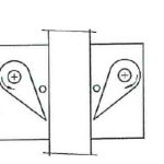
The next important development, according to Grierson,[3] was cam-type guide grips that appeared around 1893 and were still extensively in use in the U.K. (Bear in mind Grierson was published in 1923.) It consists of four serrated steel cams mounted on two turned steel rods that, when the necessity arises, rotate and bring the cams into contact with the guide rails or wood backing.
This safety gear was only suitable for slow (100 fpm) cars due to being of practically instantaneous action. The design would also only protect against a too-rapid descent of the lift car and was useless for excessive speed in the upward direction. Grierson noted that various manufacturers used different methods of safety-gear activation, including slack-rope activation and a separate safety line connected between the car and counterweight.
In 1878, an overspeed governor of the flyball type was invented for the purposes of operating a progressive safety gear. This was invented by Charles R. Otis.[1]
Safety Record
With one exception (until the Petersen paper[1] was published in 1945), there is not a single known instance of an Otis traction elevator falling because of broken ropes or for any other reason. The one exception was furnished by a single elevator in the Empire State Building in New York City on July 28, 1945. While traveling downward at about the 17th floor, all its hoisting and governor cables were severed by an airplane, which crashed through the hatchway at the 89th floor. This rendered the safety equipment inoperative. Understandably, this was not (nor intended to be) proof against airplane collision any more than a railway block system will protect a train from the remote contingency of a collision with a Flying Fortress. Happily, the operator (who was alone in the car) survived the crash. Since this incident cannot be regarded as a failure of the ropes or safety equipment, the record remains unimpaired.[1]
Development of British and European Standards
Further work into researching older standards and codes of practice is required, as there is clearly a gap between Otis demonstrating his safety gear in 1853 and the 1970 edition of BS 2655-1. It is understood that there was a BS 2655 published around 1958, but even then, this leaves a gap of more than 100 years in documentary evidence of design.
Standards since 1970 have developed as follows:
- 1970: BS 2655-1:1970: Specification for lifts, escalators, passenger conveyors and paternosters. General requirements for electric, hydraulic and hand-powered lifts
- 1970: BS 2655-7:1970: Specification for lifts, escalators, passenger conveyors and paternosters. Testing and inspection
- 1979: BS 5655-1:1979, EN 81-1:1977: Lifts and service lifts. Safety rules for the construction and installation of electric lifts
- 1986: BS 5655-1:1986, EN 81-1:1985: Lifts and service lifts. Safety rules for the construction and installation of electric lifts
- 1986: BS 5655-10:1986: Lifts and service lifts. Specification for the testing and inspection of electric and hydraulic lifts
- 1995: BS 5655-10.1.1:1995: Lifts and service lifts. Specification for the testing and examination of lifts and service lifts. Electric lifts. Commissioning tests for new lifts
- 1995: BS 5655-10.2.1:1995: Lifts and service lifts. Specification for the testing and examination of lifts and service lifts. Hydraulic lifts. Commissioning tests for new lifts
- 1998: BS EN 81-1:1998 + A3:2009: Safety rules for the construction and installation of lifts. Electric lifts
- 1999: PAS 32-1:1999: Specification for examination and test of new lifts before putting into service. Electric traction lifts
- 1999: PAS 32-2:1999: Specification for examination and test of new lifts before putting into service. Hydraulic lifts
- 2007: BS 8486-1:2007+A1:2011: Examination and test of new lifts before putting into service. Specification for means of determining compliance with BS EN 81. Electric lifts
- 2007: BS 8486-2:2007+A1:2011: Examination and test of new lifts before putting into service. Specification for means of determining compliance with BS EN 81. Hydraulic lifts
- 2014: BS EN 81-20:2014: Safety rules for the construction and installation of lifts: Lifts for the transport of persons and goods. Passenger and goods passenger lifts
- 2014: BS EN 81-50:2014: Safety rules for the construction and installation of lifts: Examinations and tests. Design rules, calculations, examinations and tests of lift components
Factors Affecting Safety-Gear Design
Several factors seem to have driven safety gear design over the years:
- The desire to prevent an uncontrolled descent
- The relationship between speed and safety gear design (principally to protect passengers against injury)
- The desire to protect against uncontrolled ascent
- As the research progresses, more categories may be identified, although it currently appears that from 1853 onward, for over a century, it was simply a desire to prevent uncontrolled descent to allay passenger fears about this risk.
1970: BS 2655-1:1970
BS 2655-1:1970: Specification for lifts, escalators, passenger conveyors and paternosters. General requirements for electric, hydraulic and hand-powered lifts were published in 1970 and ended up with six amendments. There were four separate sections on safety-gear requirements, which could be found in sections 2, 3, 5 and 6. It stated that safety gears shall comply with the following general requirements:
- Every passenger and goods lift shall be provided with a safety gear attached to the car frame and placed beneath the car platform.
- A safety gear shall also be provided on the counterweight where there is an accessible space beneath the travel of the counterweight.
- It shall be possible to release car safety gears by raising the car and counterweight safety gears by raising the counterweight.
- Each car safety gear shall be operated by means of either a governor or a safety rope.
- All sheaves or pulleys in contact with any part of this rope, which is normally in motion at the same time as the car, shall have diameters at least 30 times the diameter of the rope.
- A car safety gear shall not operate to stop an ascending lift car. If an ascending lift car is to be stopped because of overspeed, a safety gear shall be fitted to the counterweight for this purpose. Where an overspeed governor is used, it shall cause the motor- and brake-control circuits to be opened in the event of overspeed in the upward direction.
- The application of the safety gear shall not cause the car platform to slope at more than one in 25 to the horizontal.
- The motor- and brake-control circuits shall be opened by a switch on the car safety gear before or at the time the safety gear is applied.
- When the car safety gear is applied, no decrease in the tension of any rope used for applying the safety gear or motion of the lift car in the downward direction shall release the car safety gear.
- It shall not be possible for vibration of the car frame to cause a safety gear to be applied.
- No safety gear shall depend for its operation upon completing or maintaining an electric circuit.
- The gripping surfaces of a safety gear shall be held clear of the guides during normal operation of the lift.
- Any levers or cams operated by shafts shall be fixed to such shafts by means of welding, sunk keys or an equivalent positive connection.
- Safety gears shall be designed to grip each guide and operate on the guides simultaneously.
- Any shaft, jaw, wedge or support that forms part of a safety gear and which is stressed during its operation shall be made of steel or other ductile material.
- The drive to a car governor rope shall be effected from the car frame.
- Any connecting device between a governor rope and car frame (or counterweight) intended to be released when the safety gear is applied shall be retained in its normal position by a spring-loaded device.
- A pawl and ratchet shall not be used as a safety gear.
BS 2655-1 (1970)
BS 2655-1: Lift speed and safety gear selection stated in 2.12.3: “Safety gears of the instantaneous type may be used for lift cars having a contract speed not exceeding 0.75 mps or 150 fpm.”
BS 5655-1 (1979)
There was a shift in the 1979 standard, which introduced the buffered effect for the first time:
“9.8.2.1 Car safety gear shall be of the progressive type if the rated speed of the lift exceeds 1 mps. It can be (a) of the instantaneous type with buffered effect if the rated speed does not exceed 1 mps [or] (b) of the instantaneous type if the rated speed does not exceed 0.63 mps.”
The buffered effect was rarely used, but, when it was, it involved the sling having an additional and independent traveling section underneath it, which had an instantaneous safety gear attached. This safety gear would operate, and the forces were reduced by the car sling being separated from the safety gear by devices such as hydraulic pistons (rather like buffers) which would take the forces out of the operation.
Different manufacturers came up with different designs for both instantaneous and progressive safety gears. Examples of different arrangements from different companies can be seen in Figures 5 and 6.
BS 5655-1 (1986) and EN 81-1 (1990) + A3 (2009)
These standards mirrored the BS 5655-1 (1979) standard.
EN 81-20 (2014)
The publication of EN 81-20 (2014) saw the end of the buffered effect, with the wording being amended as: “5.6.2.1.2.1 Car safety gear (a) shall be of the progressive type or (b) may be of the instantaneous type if the rated speed of the lift does not exceed 0.63 mps.”
The philosophy behind the change in speed between the 1970 and 1979 standards for instantaneous safety gears is not known. However, it can be seen that the EN 81-20 (2014) standard limits instantaneous to a maximum speed of 0.63 mps, whereas BS 2655-1 (1970) allowed the higher speed of 0.75 mps. So, despite the buffered effect being removed, the reduced speed from the 1979 standard is still adopted.
Forces
Initial inferences were that considerations with respect to forces imposed on passengers may have caused the change. The standards do not specifically state forces applied on a passenger during the operation of a safety gear. The best that can be referred to is the forces permissible in the event of a buffer collision.
BS 2655-1 (1970)
BS 2655-1 (1970) simply stated in clause 3.4: “Buffers shall be installed under all cars and counterweights. Springs buffers or buffers of rubber or timber may be used.”
This is a completely meaningless statement by today’s standards, but, clearly, there is no consideration as to the forces permitted to be placed upon a passenger, nor distinction between instantaneous or progressive safety gears. It should be noted that timber buffers were permitted.
BS 5655-1 (1979)
BS 5655-1 (1979) saw the introduction of consideration into forces imposed on a passenger. Clause 10.4.3.3 stated:
“With the rated load in the car, in the case of free fall, the average retardation during action of the buffers shall not exceed gn. Retardation of more than 2.5 gn shall not be longer than 1/25 of a second. The speed of impact on the buffers to be considered is equal to that for which the stroke of the buffer is calculated (see 10.4.3.1 and 10.4.3.2).”
While the introduction of forces into the standards came with the 1979 standard, it is unlikely to account for the difference in speed with reference to safety-gear speed between the 1970 and 1979 standards.
BS 5655-1 (1986)
BS 5655-1 (1986) mirrored the 1979 standard, with the exception that the 1/25 s. was replaced by 0.04 s., thus eliminating the fraction for a decimal.
Direction of Lift and Safety Gear Selection
BS 2655-1 (1970)
As previously stated in BS 2655-1 (1970): “A car safety gear shall not operate to stop an ascending lift car. If an ascending lift car is to be stopped on account of overspeed, then a safety gear shall be fitted to the counterweight for this purpose.”
BS 5655-1 (1979)
The wording changed in the 1979 standard to the following:
“9.8.1.1 The car shall be provided with a safety gear capable of operating only in the downward direction and capable of stopping a fully laden car, at the tripping speed of the overspeed governor, even if the suspension devices break, by gripping the guides and holding the car there.”
It should be noted that the overspeed governor was introduced into the wording of standards as a mandatory clause for all electric lifts, including those with instantaneous safety gears, albeit, as previously mentioned, Charles Otis invented the flyball overspeed governor for progressive safety gears in 1878.
Prior to this, BS 2655-1 (1970) offered an overspeed governor as an option as follows:
“2.12.3 The safety gear shall operate to stop and sustain the lift car with contract load in the event of failure of all suspension ropes or chains or their attachments or in the event of the lift car exceeding a predetermined speed in the downward direction when the safety gear is operated by an overspeed governor.”
BS 5655-1 (1986)
BS 5655-1 (1986) adopted the same wording as the 1979 standard.
EN 81-1 (1998) + A3 (2009)
It was not until EN 81-1 (1998) Amendment 3 (2009) that the requirement to stop an ascending lift car came into being with clause 9.10, which stated:
“9.10 A traction lift shall be provided with ascending car overspeed protection means conforming to the following:
9.10.1 The means, comprising speed monitoring and speed reducing elements, shall detect uncontrolled movement of the ascending car at a minimum 115% of the rated speed, and maximum as defined in 9.9.3, and shall cause the car to stop, or at least reduce its speed to that for which the counterweight buffer is designed.”
EN 81-20 (2014) varied the wording to:
“5.6.1.1 Devices, or combinations of devices and their actuation, shall be provided to prevent the car from (a) free fall, (b) excessive speed, either downwards, or up and down, in the case of traction lifts, (c) unintended movement, with open doors [or] (d) in the case of hydraulic lifts, creeping from a landing level.”
Conclusion
The history of the safety gear is an interesting subject, and it has been identified that there is a long gap of inactivity in design from 1853 to 1970 that requires further investigation. Sources thus far identified show development from a state of concern about the risk of falling to the quality of the fall, should it happen with the introduction of acceptable forces relative to speed. Furthermore, the need to address other technical issues such as uncontrolled movement in the ascending mode have also caused developments in safety-gear design. Research will continue to establish development of the safety gear from its initial design in 1853 to the present day.
-
- Figure 1: Early design of a safety gear using knives that dug into wooden guides[2]
-
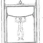
- Figure 2: Italian invention with rods above passengers’ heads[2]
-
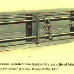
- Figure 3: Waygood-Otis instantaneous safety gear[3]
-
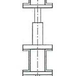
- Figure 4: Buffered-effect safety gear with a buffer between the car and safety gear[2]
-
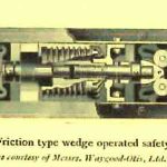
- Figure 5: Waygood-Otis wedge-type progressive safety gear
-
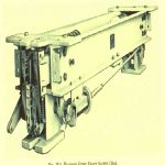
- Figure 6: Express Lifts clamp-type progressive safety gear[9]
References
[1] “Elisha Graves Otis 1811-1861 and His Influence Upon Vertical Transportation,” presentation to the Newcomen Society American Branch in New York (1945).
[2] John Inglis. “Evolution of Safety Gear,” presented at Elevcon 2 (1998).
[3] Ronald Grierson. Electric Lift Equipment for Modern Buildings, Chapman & Hall (1923).
[4] BS 2655-1 (1970).
[5] BS 5655-1 (1979).
[6] BS 5655-1 (1986).
[7] EN 81-1 (1990) including Amendment A3.
[8] EN 81-20 (2014).
[9] R.S. Phillips. Electric Lifts, Pitman Publishing (1973).
Get more of Elevator World. Sign up for our free e-newsletter.


