KEB dV/dt Elevator Chokes: Protect your Elevator Motor Investment
Mar 1, 2012
This article provides an explanation of the effects of high dV/dt created by variable-frequency drives and offers solutions to protect elevator motors.
submitted by KEB America, Inc.
During the past 20 years, AC variable-frequency drives (VFDs) have gained widespread acceptance in elevator applications. Overall, AC elevator drives provide im-proved ride performance, increased system efficiency and advanced controller reliability. However, the use of VFDs does not come without side effects, one of which is high dV/dt, or voltage increases. This article provides an ex-planation of the effects of high dV/dt created by VFDs and offers solutions to protect elevator motors.
What Are dV/dt Spikes?
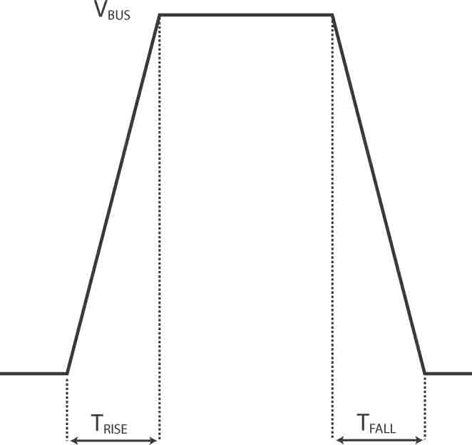
Most commercial AC elevator VFDs use a technology called pulse-width modulation (PWM) to simulate a three-phase AC sinusoidal voltage output. PWM operates by rapidly turning the drive’s output insulated-gate bipolar transistors (IGBTs) on and off, modulating the drive’s DC bus voltage. When the IGBT is closed, the voltage at the VFDs’ output terminal increases to that of the DC bus (Figure 1). The change in voltage is not instantaneous but ramps up to the DC bus level over a given time (TRISE). The rate at which the voltage increases is referred to as dV/dt rise time and is a characteristic of the transistor design.
Motor Cabling and Reflected Wave
The motor cabling between the elevator drive and motor has characteristic impedance, which depends on the cable length and physical properties of the cable ma-terial. The motor cabling acts as a transmission line and propagates the drive’s output voltage to the motor. If the impedance of the motor and cabling are not matched, a wave reflection will occur at the motor load. This results in a voltage overshoot or “ringing” at the motor terminals and a reflected wave back to the drive (Figure 2). In a worst-case scenario, the reflected wave could be added to the fundamental waveform coming from the drive, result-ing in a significantly higher voltage at the motor termi-nals. Longer motor leads have larger impedances, ulti-mately increasing the voltage at the motor leads. For this reason, it is best to mount the motor and drive as close together as possible.
Switching Frequencies
Operating at higher switching frequencies in elevator applications is desirable, because it reduces audible noise made by the VFD, while providing the motor with a higher-quality current waveform, which results in lower motor losses. When AC VFDs were first commercially applied in elevator applications, the transistors were typically cycled at a frequency around 2 kHz. As technology improved, transistors with higher dV/dt rise times became avail-able, allowing operation at higher switching frequencies. Today, most elevator drives operate at 8 kHz switching frequency as standard, with the option to run up to 16 kHz when required by the application. It is important to note that higher switching frequencies require the transistors to turn on and off more often, exposing the motor to an increased number of high voltage peaks.
dV/dt Effects on Motor Operating Lifetime
In short, voltage peaks from high dV/dt break down a motor’s insulation and shorten its operating life. Most three-phase AC motors produced today are “inverter-rated,” utilizing wire and insulation rated to withstand peak voltages of at least 1,600 V. Certain elevator applications (480 VAC, long motor leads, 16 kHz switching, etc.) are more suscepti-ble to dV/dt failure and will experience voltage spikes in excess of the motor insulation rating. However, even if the dV/dt spikes do not exceed the 1,600 V insulation rating, repeated exposure to spikes over the motor’s life will stress and weaken the insulation. Over time, the motor insulation system could break down, resulting in a phase-phase or phase-ground short in the windings and a catastrophic motor failure. Because the drive’s peak output voltage is directly related to the DC bus level, the dV/dt spikes will be larger in 480-VAC installations compared to those in 230 VAC installation. Additional precaution should be taken to mitigate the dV/dt spikes in 480 VAC installations.
MRL Applications
A motor failure is particularly problematic in machine-room-less (MRL) applications, because the motor is located in the hoistway and is not easily accessible to be either rewound or replaced. A motor failure in an MRL applica-tion could be costly to repair and cause significant down-time. Furthermore, MRL applications are especially sus-ceptible to dV/dt spikes, because the motor often cannot be located next to the elevator drive, and the application requires long cabling runs, adding to the magnitude of the dV/dt voltage peaks.
dV/dt Mitigation and Filters
The first thing a person can do to protect an elevator motor from high dV/dt is to minimize the length of cable between the elevator drive and motor. Another option is to reduce the carrier frequency of the drive, but this is usually undesirable in elevator applications, since it intro-duces audible noise. If neither option is possible, a con-sultant should consider specifying a dV/dt filter (or choke), which will decrease the dV/dt rise time and reduce peak voltages at the motor.
A dV/dt filter is placed directly at the output of the el-evator drive and limits the rate of change of the voltage (dV/dt) to a level characteristic of the filter design. It is important that the filter is placed as close to the output of the drive as possible so the voltage peaks are not propa-gated through the motor cabling. Unless the motor and cabling impedances are matched, the standing wave re-flection could still occur, but the negative effects are dra-matically minimized by the filtering of the dV/dt spikes.
KEB dV/dt Filters
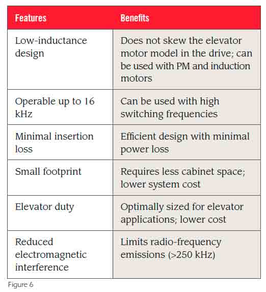
KEB has worked closely with the elevator industry for more than 20 years and currently offers its second genera-tion of dV/dt elevator filters. KEB filters are designed specifi-cally for elevator applications. Some of the design features of KEB dV/dt elevator filters can be found in Figure 6.
PM/MRL Applications
It is important to note that KEB dV/dt chokes are de-signed to have low impedance to not skew the drive’s inter-nal motor model. Standard output inductor chokes having 2-3% impedance can greatly affect motor performance, resulting in reduced peak torque, difficulty reaching con-tract speed at full load and general motor control instabil-ity. As a rule of thumb, KEB recommends the use of a dV/dt filter for all MRL applications where the motor is located more than 40 ft. from the elevator drive.
Frequently Asked Questions
- Q: When do I require a dV/dt filter?
- A: KEB recommends the use of a dV/dt choke for all installations where the motor is located 40 ft. or more from the drive. Using a dV/dt choke in closer installations is recommended but optional.
- Q: Can I use KEB dV/dt chokes with other drives?
- A: Yes. Because KEB dV/dt chokes have low induc-tance they should not affect the drive’s ability to measure motor parameters during an automatic tune or skew the internal motor model.
- Q: Can I use a standard motor choke to mitigate high dV/dt on an elevator application?
- A: This is not recommended. The high inductance and capacitive coupling found in these chokes will still result in high dV/dt, while limiting the motor’s peak torque dur-ing acceleration.
- Q: Can I use KEB dV/dt chokes for either PM gearless or induction geared machines?
- A: Yes. The KEB choke effectively limits voltage tran-sients in both applications and does not negatively affect the operation of either motor.
- Q: Can I use KEB dV/dt chokes for either 230-V or 480-V applications?
- A: Yes. Chokes are designed to be used for voltages up to 550 VAC.
- Q: How much does a KEB dV/dt choke cost?
- A: The dV/dt choke is typically 1-3% of the cost of the elevator motor. This represents a small investment upfront to prevent a costly repair or replacement in the future.
Get more of Elevator World. Sign up for our free e-newsletter.


