Landing Door Locking Devices
Feb 1, 2022

Introduction
Article 5.3.9.3.4 of EN 81-20 says, “In the case of landing doors driven by the car door, if the landing door becomes open for whatever reason when the car is outside the unlocking zone, a device (either weight or springs) shall ensure closing and locking of the landing door.” The relevant article indicates the intensity of the risk that may occur when the landing doors become open. Although there are different landing door locking device designs and installations, we may take a common track, which may be considered an approach that includes the design method in technical terms and benefit analysis in terms of cost, for analyzing the choices. The purpose here is to determine an optimum landing door locking device with a holistic approach.
Available Methods
Landing door closing and locking devices can be modelled as a complete mechanical system. The main components of this system are the moving mass of the landing door and a system element that accumulates energy. Generally, extension spring or a fixed weight is used for this system element. Kinetic energy generated by the movement of the landing door in the opening direction is kept as potential energy by the energy accumulating element (spring or fixed weight) of the system. This potential energy should be big enough to overcome the inertia of the total moving mass and to close and lock the door. In order to generate sufficient potential energy, a proper design for the energy accumulating system is highly critical. Otherwise, security gaps will be inevitable.
2.1 Springs
2.1 .1 Spring Design
Extension springs store energy with external energy. In operating conditions where they do not exceed elastic deformation limit, springs will use the stored energy for closing the panels completely with minimum loss. Minimum force for closing and locking the landing door should be determined. Dynamic analysis method can be used for this calculation. In order to maintain safety and security, these measurements should be done at minimum door clearance, which is also the minimum preloading distance on the spring. Extension spring design will vary based on component condition and spring characteristics. In extension spring design, wire thickness, spring outer diameter, free length, spring material, number of active coils, hook type and external force operating range should be determined.
With these design input we may reach limiting force values, spring constant, minimum and maximum load stress, required preloading force and maximum spring length. For determined forces and spring properties, a dynamic analysis is needed again in the design program. Operation limits of the landing door, friction force value and the spring properties are defined on the analysis. With these definitions, results can be created and interpreted before carrying out experimental methods through Panel Position – Time chart, Panel Speed-Time chart and Spring Force-Time chart.
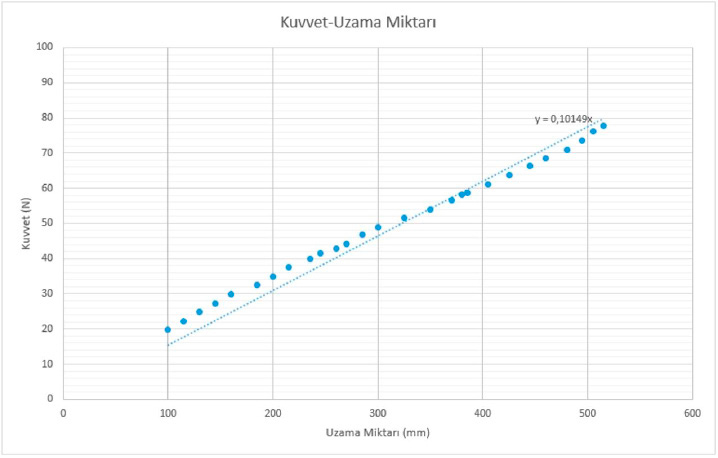
Extension springs that are theoretically designed and analyzed are then experimentally tested with a prototype. During the determination of the experimental spring constant (k), the amount of elongation at a certain force is examined through free weight spring test system.
The force applied on the spring (F) is plotted as a function of the change in spring length (x). A linear line that fits the data points is drawn and the equation of this line is shown on the chart. The curve in the force – extension amount chart gives the “experimental” spring constant (k=k’) value.
For optimum use of spring where the flexibility potential energy of the spring overcomes the friction force on the landing door and panel weights, below mentioned issues should be considered:
- Spring length should not exceed the elastic deformation limit
- Required pre-loading should be done
- Friction force should be determined
- Design results for the spring to be used should be determined
- Flexibility potential energy of the spring should be calculated
- Suitable installation positions should be determined.
- Flexibility potential energy formula is: E=1/2 k.x²
- Spring constant (k), should be determined based on the spring characteristics.
- The amount of elongation (x) indicates the energy accumulated on the spring in case of a clearance where the preloaded spring and panel is released.
- Friction force for the panels FS=kS .m .g
- Friction coefficient (kS ), Force variation measurements made experimentally through dynamic analysis,
- Panel weight (m).
- Gravitational acceleration (g)
With these calculations, appropriate extension spring selection will be determined experimentally and theoretically.
2.1 .2Advantages and Disadvantages of Springs
While using a spring for a landing door closing device is cheaper than using a fixed weight, it is risky in terms of the dynamics of the door mechanism because spring force also varies according to the changing position of the door in the opening direction.
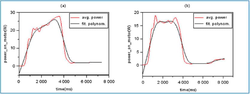
Potential energy accumulated of the spring when the car is outside the unlocking zone creates the minimum force required for closing and locking the landing door, as stated in Article 5.3.9.3.4 of EN 81-20. When the door is completely open, potential energy accumulated on the spring produces much more energy than the amount to meet the requirements of the standard. Potential energy, which varies in the opening direction of the door, affects the dynamics of the cabin door operator. While the spring force on the car door operator in the opposite direction increases during the opening movement of the door, the operator is forced unnecessarily. During the closing movement of the door, a decreasing spring force, which accelerates the door unnecessarily and makes it difficult to control the car door operator.
In Graph 2, experimental results obtained in previous R&D studies are given and dynamic impacts of using springs and fixed weights are demonstrated in numbers.[1] According to this data, the force produced by the door operator using a spring is 24% higher than the force produced by the door operator using fixed weight.
2.2 Fixed Weight
2.2.1 Fixed Weight Design
Fixed weight, which is displaced parallel to the movement of the landing door in the opening direction, operates against the gravitational force. When it is released, the weight exposed to gravitational force attempts to close the landing door panels. Since the force created by the fixed weight in the closing direction is the same in every position of the door, determining the fixed weight amount is the only critical parameter for the design. In order to determine this parameter, finding the value of the friction force that prevents the movement of the total mass is sufficient. The weight calculated by dividing this force into gravitational acceleration gives the minimum value required for the fixed weight.
2.2.2 Advantages and Disadvantages of Fixed Weight
Using fixed weight for the closing device of the landing doors is the most advantageous practice in terms of system dynamics. Instead of variable forces that have an impact on the car operator when spring is used, here we have a fixed force independent of the position of the door in the opening or closing direction. Additionally, it is more costly because of the way the fixed weight is integrated to the door mechanism. The spring is integrated by mechanically connecting one end of the spring to a fixed point on the mechanism, and the other end to a moving part on the mechanism while simple mechanical arrangements will not be sufficient for integrating fixed weight. Fixed weight that moves simultaneously with the movement of the door should be guided within the construction of the door. Since extra components are be needed, cost will increase directly.
2. Conclusion
Both methods, used in order to fulfill the requirements of the standard, may be implemented differently in each door system, and may have different implications. Therefore, there is no absolute right choice. The impacts of the choices should be examined both technically and financially. The benefit-cost ratio of the applied methods is the most basic indicator that will determine the accuracy of the choices. Therefore, devices used for closing the landing doors can be optimized by engineering in the light of this indicator.


Get more of Elevator World. Sign up for our free e-newsletter.


