Lift Modernization: the Lost Art of Engineering
Feb 1, 2016
How to deal with the limitations and design characteristics of aging lift equipment
by Roger Howkins and Kate Hibner
 This paper was first presented at the Fourth Symposium on Lift & Escalator Technologies, www.liftsymposium.org.
This article investigates the techniques and tools available to the lift modernization engineer and uses case studies of lift forensic engineering, codes used for imported lifts, reliability impact testing of door systems and ride quality. The experienced lift modernization engineer needs to understand the limitations and design characteristics of the aging lift equipment being considered and how it can be blended with new engineering components and systems, and original and current code requirements. Also, the structural limitations of the building have to be considered for lift equipment removal, routes (possibly across floor slabs) and the suitability of lift shaft walls for new affixing means.
In his Lift Modernisation Design Guide, Roger E. Howkins explains:
“The lift modernization designer asks, ‘When is a lift system old?’ ‘When does it require a transplant, brain surgery or facelift?’ in other words, ‘a modernization.’ Lift companies, architects and consultants use various terms to describe a lift modernization, i.e., conversion, retrofits, renovating, changeovers or upgrading.”[1]
The Situation
At recent lift conferences and symposia, a high proportion of papers and poster sessions (approximately 30%) have been devoted to the system approach to lift performance as defined by lift traffic-analysis research. The next-highest number of papers were devoted to mechanical and electrical design with a bias toward traffic control and green issues. Worryingly, all of these papers generally focus on the “new build” systems, rather than the existing lift stock.
According to the published data as of March 2010, there were an estimated 4.5 million units installed within Europe, with approximately 207,000 of those in the U.K.[2] Within the U.K., there are an estimated 114,000 lift units that were installed prior to 1986.[3] Depending on the design of the original equipment and how it was maintained, these units may be coming to the end of their useful theoretical design life. The majority of these existing units are in small buildings, where the constraints of a lift modernization are the existing lift shaft, the size of machine rooms and any equipment that could be reused, refurbished or modernized.
Within Europe, an estimated 64% of the lifts currently being maintained have been installed in residential buildings and only 14% within offices. Therefore, it appears that a considerable amount of effort and time is being used to carry out lift system analysis on a small proportion of the European lift stock.
When confronted with an existing lift, the majority of lift manufacturers do not consider modernization as an option for improvement. They prefer to install “standard” units from a catalog, rather than take up the challenge of keeping the old equipment and bringing it back to its original design standard.
In Poland, the existing lift stock is considered to be 81,683 units, and it has been estimated that there are more than 25,000 units there that are at least 60 years old.[4] These units have had no modernization and have a level of original design and craftsmanship that is difficult to achieve today. If Poland decided to replace these historic lifts with new EN 81 lifts, it would rightly be considered an act of historic vandalism.
This does not necessarily reflect on the skills and the expertise of the design engineers and field technicians who specialize in new lift installations, but a concern remains that the skills and the expertise of lift modernization is not being transferred to the younger engineers and technicians employed by companies — consultants, mechanics and technical sales engineers alike.
Limitations
Lift modernization demands the skills of an engineer with the subtleness of an artist. It could also be described as a “technical cookbook” where all of the ingredients can be found, but unless they are blended correctly in the right proportions, the results of the finished lift modernization could end up being worse than the condition of the system before the works were carried out.
Nowadays, the “new lift installation” sale transaction is dictated in the form of the standard company product range, which has no room for change or compromise, because of the way the manufacture and type-testing procedures are set up and carried out.
Skilled lift modernization engineers are not constrained by limitations that come with a new lift installation. They have much more of a “blank canvas” approach toward components or materials that can be used and blended into a design. A good modernization project has an important advantage: the lift does not lose its character but retains or improves on important technical and safety aspects from when it was originally installed.
A savvy modernization engineer can restore a lift to its original specification and still provide a safe and reliable installation that could outlast a modern lift product from a standard generic range. Older lift equipment has a proven design and manufacturing process, highly reliable and robust components and a high probability of survival. New lift installations tend to be much more complicated and consist of complex components and subsystems designed to ensure competitiveness, rather than longevity.
Mission Critical
Just because a lift is “old” does not mean it has to be unsafe or unreliable. Instead, what has to be considered is whether this lift can fulfill its function to transport passengers and goods safely and reliably. Therefore, we have to consider mission-critical systems that may require modernization. These systems include components and subsystems in the lift motor room and hoistway, information systems, as well as primary safety systems. The mission-critical components include but are not limited to gearless machines, worm-gear drives, controllers, selectors, pulleys, door drives, overspeed governors and safety gears.
Just because an individual lift subsystem or component wears out, does not mean the total assembly needs to be replaced. There are specialized manufacturing companies that supply components for old lifts with the same design and safety characteristics as the original components.
Forensic Engineering
The modernization engineer must be aware of code or standard recommendations to reduce energy consumption but should not be restricted by modern technology, traffic handling or aesthetics. Wooden lift cars with wrought-iron enclosures and stained-glass decoration, and lifts with original machines and mechanical equipment do not need to be mission critical if a sensitive modernization and restoration process is undertaken. Since a standard modern lift typically cannot be sensitively blended into an historic environment, a modernization engineer should utilize the tool of forensic engineering.
Forensic engineering is considered to be “the investigation of materials, products, structures or components that fail or do not operate or function as intended, causing personal injury or damage.”[8] Consequently, the forensic investigation aims to locate causes of failure with a view to improve performance or extend the life of a component.
In the lift motor room, the components considered to be mission critical are the motor and gearbox assembly, and controller. There may also be an overspeed governor, which could be “old” and not up to the current code requirements. However, as long as it operates in accordance with the code applicable at the time of installation, it should match with the safety gear installed.
When considering the geared or gearless machines, some even older than 50 years, the simple option would be to remove them, along with any associated problems and blending the new equipment with the existing structural steel bedplate. This would require a structural analysis of the original bedplate plate design, as the new equipment load paths could vary dramatically from the existing structure. The new arrangement, however, will very likely deflect, causing premature failure of the new equipment. On the other hand, if modernization is considered, the equipment load paths would remain the same, requiring reduced design development and lower capital costs. This would be a much more cost-effective solution.
It is very difficult or nearly impossible to visually inspect the internal components of a worm-geared traction machine and give an assessment of the expected remaining life expectancy for the unit.[5] In such a case, it is recommended that a forensic engineering survey is carried out on the unit(s).
A considerable amount of information can be obtained from the analysis of oil and grease taken from the gearbox reservoir and bearing housings. Also, non-destructive testing techniques could be undertaken, such as thermal imaging on bearings. The alternative means of extracting such information would require destructive testing or sending the unit back to the original manufacturer, assuming it is still in business.[5]
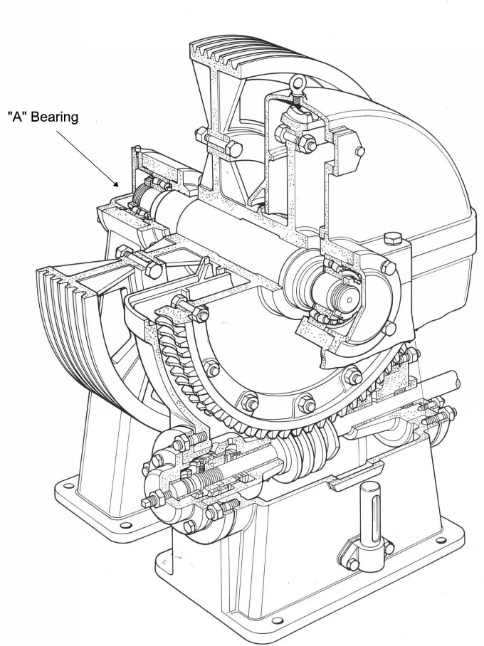
An example of such an analysis (Table 1) shows that the oil sampled was either replaced at some point or contaminated with an unsuitable grade, or the lubricant has deteriorated over time. The forensic investigation showed that fairly significant levels of ferrous debris were present. Further investigation showed that the “A” bearing had failed (Figure 1). Such detailed information could not have been obtained from a visual inspection or without dismantling the machinery.
The forensic analysis also showed high levels of wear-metal elements (copper [Cu] and tin [Sn]) in both samples. These metals originated from the sliding friction between the phosphor bronze worm wheel and the worm shaft, as well as from the shaft rotation in the plain sleeve bearings. These characteristics are typical for the traditional worm and wheel traction lift winding units.
The elevator vibration analyzer is a tool that can also be classified as a forensic aid, which can be used to determine the condition of a component. It is well known that lift noise and vibration analyzers are used to determine limits of noise and vibration within a moving lift car, but they can also be used to determine from where the noise and vibration originate. The source could be the machinery, ropes, pulleys, guide rails or even guide shoes. Lateral quaking is, for example, the horizontal swaying of the car and can be caused by bends in the guide rails and/or inadequate operation of the roller or sliding guide shoes. Vertical vibrations mainly originate from the hoist machine or pulleys. It is transmitted through the ropes and can occur due to the dynamic balancing of the drive motor. The acceleration, deceleration and jerk, in turn, give the passengers a sensation of their weight increasing or decreasing and can be a result of the lift sticking to the guide rails due to high pressure and/or high friction.
Maintenance
The first truly modern use of electronics in lift controllers took place in the 1970s. Before this date, the controller was referred to as “relay logic” and was both generally simple and reliable. For office buildings, however, this type of controller did not have the quick response time demanded by the lift system engineers for the traffic patterns occurring in new office buildings. Also, this control system did (and still does) suffer when installed in a “dusty” environment made worse by lift maintenance companies reducing the time spent performing routine maintenance and adjusting the relays.
These relay logic switches are still very common and are easily maintained and repaired. Moreover, if quick electronic response times are not required, there is no real reason why they cannot be incorporated into a historic lift modernization ahead of a new microprocessor-based lift controller. Unfortunately, a less experienced lift modernization engineer will likely opt for the “easy replacement” option.
The maintenance company’s approach to the allocation of time and resources for routine maintenance has recently been typically centered on new, complex lift technology. As a result, the time allowed for each maintenance visit has been reduced to a minimum, and it is now insufficient for proper lift care, possibly preparing the customers for new lift sales driven by the existing lift reliability issues.
A Different Approach
The continuing upkeep and maintenance of the 25,000 historic lifts in Poland suggest that it is possible to preserve a higher skill base that encourages the remanufacture of components to match their original design and specification. This also suggests that the engineers and architects understand the social need for modernization.
Poland’s large skill base actively pursuing the modernization of its many old and historic lifts is no reflection on the skill of the younger lift engineer, but living proof that there is a room for both the restoration engineers and the standard new-installation lift engineers within our industry.
Codes, Standards and Good Practices
It is only in relatively recent times that codes and good-practice guidelines for lifts have been published. In the U.K., BS 2655: Part 3 (1971)[6] (superseded in 1989 and replaced by EN 81-3:2000+A1 2008[7]) sets out the recommended arrangements for standard electric lifts in metric units. Prior to this date, the units for manufacturing, installation and buildings were in the Imperial measurements of feet and inches. This date is important to the original understanding of design limitations of lifts installed in the U.K. The lifts could have originated from a British manufacturer; a European supplier; or, as in the case of prestigious, relatively tall buildings at the time, the U.S., which (although using Imperial units of measurement) would use American National Standard screw threads, which would be not compatible with the British Standard screw threads or spanners.
Prior to the European Lift Directive being put into practice, there had been lift installations fully imported from other countries, such as Japan. In these instances, the code of manufacturing and component design had followed the Japanese Industrial Standards (JIS). These lifts will require modernization in the near future. Consequently, it has to be assumed that the components of these installations will have different design characteristics than those of modern components, thus requiring a detailed site investigation and inspection of all components for wear, damage and proper installation.
Another example of conflicting codes is a situation where a lift guide rail has a bend that has probably been there since installation and needs to be replaced. The modernization engineer is faced with the decision of whether to remove the damaged rail and lower the sections above the damaged section so the keyways slot into place (as they have the same design characteristics). To which specification should the new rail ascribe? Should it be to ISO 7465:2007? Was it a British guide rail with Imperial dimensions, an American one made to A17.1 or a Japanese one made to the JIS standard?
It is still possible to find lifts with wooden or round car or counterweight guide rails, which, although not compliant with modern code, have probably given more than 60 years of reliable service, while correctly matched with a compatible safety gear. Removing and replacing this type of guide rail with modern T-section guide rails would require a full structural assessment of the shaft walls, as well as possibly a new car sling and car.
In the majority of instances, re-fixing or repositioning of lift guide rails in an old lift shaft, which were mainly constructed in masonry, can be a real design challenge, not only for the guide brackets, but also door frames, as the existing construction cannot always be properly identified and assessed.
The lift modernization engineer, when confronted with shaft walls of unknown construction, has several design options, depending on the fixings being considered. In any case, loading tests should be carried out onsite, where a load application device is used to test the masonry to see if it detaches from the bond.
Final Thoughts
Just because a lift is being modernized, does not mean that it cannot comply with the requirements of universal access. Although the physical size of the lift can have an effect on full lift compliance, and the repositioning of the car-operating stations can destroy the architectural features of wooden decorative lift cars, the introduction of modern LCD indicators would be totally out of character with the old lift. Therefore, the lift modernization engineer must not only be a skilled engineer who understands the limitations of the lift being modernised, but also one aware of the options available and understand which components can be overhauled or remade. Probably the most important virtue he or she must possess is to be a sympathetic lift conservationist so the specified modernization works do not end up being nothing more than historic vandalism.
Acknowledgement
The authors would like to thank all colleagues at Arup for all their advice, assistance and, more importantly, their enthusiasm for promoting the modernization of lifts.
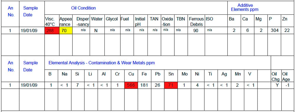
Table 1: An oil analysis report provides specific site inspection information and an estimation of the oil condition by detailing its state, presence of additive elements and an elemental analysis of the oil contamination by potential wear metals. 
Figure 1: Sectional perspective of a single worm-geared machine[1]
References
[1] Roger E. Howkins. Lift Modernisation Design Guide, Elevator World, Inc., 1998.
[2] British Standard 5655-11, 2005.
[3] E4 — Energy Efficient Elevators and Escalators. “Intelligent Energy — Europe,” March 2010.
[4] John Gale. “EURO-LIFT 2012 in Kielce, Poland,” ELEVATOR WORLD, February 2013.
[5] “Guidelines on the Supplementary Tests of In-Service Lifts,” SAfed LGI — Safety Assessment Federation, February 2006.
[6] British Standard 2655, Part3: 1971.
[7] European Norm 81-3:2000+A1 2008.
[8] Wikipedia. “Forensic Engineering” (en.wikipedia.org/wiki/Forensic_engineering).
Get more of Elevator World. Sign up for our free e-newsletter.

