Motor Controllers
Aug 1, 2015

Types, requirements, and diagnostics and repair are among the aspects of motor controllers this overview addresses.
The National Electrical Code (NEC), which has jurisdiction over subjects in which it has been enacted into law, specifies that any electric motor must have a controller. A motor controller may perform a multitude of functions. A principle purpose is to provide a means to disconnect the motor from the source of power. This can happen either automatically or manually at the direction of the operator. It can take place in the event of excessive motor temperature, current flow in the supply conductors, binding or malfunction in the load, or for any reason for which it is specified. In an elevator installation, for example, the motor will not run when a door sensor indicates a car door is open.
Besides starting and stopping the motor, controller functions include choosing forward or reverse rotation, controlling the speed and torque, and protecting against overloads and faults. That is just a partial list. The complexity and amount of functionality exhibited by a motor controller can rival that of a personal computer. One example is the programmable logic controller (PLC), and another is the elevator motion controller. There is no hard and fast dividing line between either of these and a motor controller.
Regardless of the level of sophistication, all of this equipment, in the U.S. and other areas where it has jurisdiction, must comply with the NEC. Since that is a good starting point for designing a motor installation, this article will take a look at the principle requirements.
Motor-control circuits are covered in Part VI of “NEC Article 430: Motors, Motor Circuits, and Controllers.” Part VII covers motor controllers. An important subtopic in the section on motor-control circuits is overcurrent protection. It is important that ampacity be calculated correctly when specifying the conductors that supply power to a motor controller. Of course, the amount of current drawn by the controller is less than the amount of current drawn by the motor, but if the conductors are undersized, there may be a fire hazard. And, if the controller fails due to an improperly designed power supply, the motor will experience an outage. Results can range from inconvenience and loss of productivity to profound danger, as in the case of a fire-pump motor that does not work as expected. For this reason, an exception in the NEC states that for control circuits for which their openings would create a hazard, the conductors require only short-circuit and ground-fault protection, and are permitted to be protected by the motor branch-circuit, short-circuit and ground-fault protective devices. This is assuming the usual scenario, which is that the motor-controller power supply is tapped from the load side of the motor branch-circuit protective device.
Overcurrent Protection
Overcurrent protection for motors is somewhat more complex than for other types of loads, due to the fact that there is such a heavy startup current. All loads are like that, but motors are even more so. The inertia of rest has to be overcome and the rotor brought up to speed before the current flow into the rotor and/or stator becomes stabilized. This is a far greater task than bringing an incandescent bulb up to full brightness. Consequently, there is a severe overcurrent protection dilemma. If conventional overcurrent protection is provided, as for non-motor loads, a few seconds after initial startup (before the motor reaches rated speed), the breaker will trip.
To resolve this difficult situation, a two-tier overcurrent protection scheme, permitted for motors only, has evolved. The overcurrent device at the upstream end of the branch circuit, either in the entrance panel or at the downstream end of a feeder in a distribution box, is permitted to be at a much higher (less sensitive) level than would be used for other types of loads. This breaker or fuse is intended to protect the branch-circuit conductors in the event of short-circuit or ground fault only. So, what happens if there is a lower-level fault (i.e., overload at the motor)? In this event, protection is provided by a lower-level (more sensitive) overcurrent device usually located close to the motor. It is slow acting, so the motor is able to start without having the circuit trip. This overload device is frequently incorporated into the motor controller and located inside that enclosure. Neither of these two overcurrent devices alone would provide good protection for a motor, but they are quite adequate in combination. In an industrial setting, it is good practice to install the motor branch-circuit conductors in metallic conduit for additional protection against fire and shock hazard.
To determine the maximum rating of the overcurrent protective device associated with a motor-control circuit, Table 430.72(B) in the 2014 NEC lays out the values in amperes. Control-circuit conductor sizes 18-10 AWG are correlated with maximum ratings of overcurrent devices in amperes. There is an additional category where the conductor size is larger than 10 AWG. Three conditions are specified in separate columns:
- Column A: Separate protection is provided.
- Column B: Motor-controller conductors are within an enclosure where protection is provided by the motor branch-circuit protective device.
- Column C: Motor-controller conductors extend beyond the enclosure where protection is provided by the motor branch-circuit protective device.
Each condition is further subdivided into columns covering copper and aluminum (or copper-clad) conductors. Note that no figure is given for 18, 16 and 14 AWG aluminum conductors, because only copper is permitted for motor controllers in these sizes.
In designing the power-supply conductors and overcurrent protection for a motor-control circuit, the table cited above and the accompanying notes should be followed carefully to ensure that the installation is in compliance. If a motor-control circuit transformer is used, the transformer is to be protected in accordance with the following guidelines:
- Where the transformer supplies a Class 1 power-limited circuit, a Class 2 circuit or a Class 3 remote-control circuit, protection is to comply with Article 725, which is a general treatment of these types of remote-control and signaling circuits, regardless of whether they are associated with motors.
- Protection is permitted (as opposed to required) to be provided in accordance with Article 450.3, which pertains to transformers at various voltages and locations.
- Control-circuit transformers rated less than 50 VA that are an integral part of the motor-controller enclosure may be protected by primary overcurrent devices, impedance limiting means or other inherent protective means.
- Where the control-circuit transformer rated primary current is less than 2 A and the overcurrent device is rated or set at not more than 500% of the rated primary current, overcurrent protection in the primary circuit suffices.
If one conductor of the motor-control circuit is grounded, the motor-control circuit is to be arranged so that a ground fault in the control-circuit remote from the motor controller will not start the motor, nor bypass manually operated shutdown devices or automatic safety shutdown devices.
Types of Controllers Required
Where covering the actual motor controllers, NEC 2014 begins with a general statement with no exceptions, requiring suitable controllers for all motors. Since almost all loads (with few exceptions, such as the motor that drives a utility meter) have overcurrent protection, the overcurrent protective device, if it is in the form of an inverse-time circuit breaker, will be sufficient in certain limited circumstances. Another type of motor controller is the simple plug-and-receptacle or cord connector associated with cord-connected motors.
To ascertain whether the installation is in compliance, it is necessary to look at the horsepower and location of the motor. For a stationary motor of 1/8 hp or less that is normally left running, such as a wall-mounted, AC-powered clock that cannot be damaged by overload or failure to start, the branch-circuit disconnecting means is permitted to serve as the controller. This is very often a simple circuit breaker or fuse. A molded-case switch is also permitted to function as a motor controller in this instance. This type of switch has the appearance of a circuit breaker, is mounted in a distribution box and receives its power from the bus bar, but, unlike a circuit breaker, has no overcurrent protective capability.
The next step up, so to speak, is the portable motor of 1/3 hp or less. An example is a carpenter’s sander or drill. An attachment plug-and-receptacle or cord connector is adequate for the motor controller. This arrangement works well, because the plug is usually in sight, close at hand and capable of quickly powering down the motor. It is easy to visually ascertain that the motor is disconnected from the source of power and will not accidentally start.
A section on controller design states that the controller is to be capable of starting and stopping the motor it controls and that it is to be able to interrupt the locked-rotor current of the motor. In other words, the motor controller must be configured to the motor it is intended to control.
It may seem obvious, but for the record, the 2014 NEC states that controllers, other than inverse-time circuit breakers and molded-case switches, are to have horsepower ratings at the application voltage not lower than the horsepower rating of the motor.
A branch-circuit inverse-time circuit breaker rated in amperes is permitted as a controller for all motors. This does not mean, however, that a single breaker, serving as the branch-circuit overcurrent device, can qualify as the motor controller. What is meant is that, properly configured and located, this type of breaker is permitted to serve as the motor controller. It must also conform, where necessary, to overload-protection requirements. Similarly, a molded-case switch properly rated in amperes is permitted to serve as a controller for any motor.
For stationary motors rated at 2 hp or less and 300 V or less, the motor controller can be:
- A general-use switch having an ampere rating not less than twice the full-load current rating of the motor
- On AC circuits, a general-use snap switch suitable only for use on AC (not a general-use AC/DC snap switch) where the motor full-load current rating is not more than 80% of the ampere rating of the switch
For torque motors, the controller is to have a continuous-duty, full-load current rating not less than the nameplate current rating of the motor.
Requirements of Controllers
It may seem bizarre to those used to wiring switches and overcurrent devices in double-pole configurations, but the controller is not required to open all (ungrounded) conductors to the motor. That is because the primary function of the motor controller is to start and stop a motor, but not necessarily to serve as the disconnecting means.
It is further stated that each motor is to be provided with an individual controller. However, there are exceptions to this rule. For motors rated 1,000 V or less, a single controller may serve a group installation where:
- Numerous motors drive several parts of a single machine or piece of apparatus, such as a woodworking machine.
- A group of motors is protected by a single overcurrent device.
- A group of motors is located in a single room within sight from the controller.
Diagnostics and Repair
Motor-control equipment can range from a single switch or cord-and-plug connection to a complex PLC, elevator motion controller or computerized sequential aerospace machinery. To perform diagnostics or repair, it is very difficult to examine the circuitry in hope of finding one or more visually defective components in all but the simplest equipment. What is needed is documentation, generally supplied by the manufacturer. This can consist of an overall description of the equipment, a list of specifications, and a troubleshooting guide, in addition to several types of wiring diagrams.
Block diagrams depict the functional constituent parts of the equipment. They are excellent gateways for acquiring an overall understanding of the unit and determining where to begin in a repair operation. It is often possible to isolate the fault to a single area by thinking about the nature of the malfunction and looking at the block diagram.
Usually, the manufacturer’s documentation includes a pictorial diagram. This will be photographs or drawings depicting and labeling the equipment as it appears visually. Pictorial diagrams usually do not show the component’s electrical connections, but they are helpful in conjunction with the schematics in locating potentially defective parts to be tested. Moreover, if there is a problem getting the unit back together after a repair, the pictorial may provide guidance.
Another type of diagram is the schematic. It shows part or all of the equipment. It depicts the components not as they appear on the actual printed circuit board or chassis, but in the context of the electrical relationships. The schematic is drawn according to various conventions that are more or less universal. The power supply comes in at the left, and outputs are on the right. Signal inputs are at the top or left of the diagram, and the ground bus or terminal is at the bottom. All of this is irrespective of the actual physical location of the components as shown in pictorial diagrams. For the technician, the schematic is the most important part of the documentation. In motor-control circuits, the power supply and its connections to the motor and control relay are often omitted in the interest of simplicity.
Another type of diagram very relevant to motor control equipment is the ladder diagram, so called because it resembles a typical ladder. On the left and right (sometimes top and bottom) are two rails. For a 240-V circuit, the left rail is “L1,” and the right rail is “L2”. For a 120-V circuit, the left rail is “Line,” and the right rail is “Ground.” Connecting the rails are one or more rungs. Each rung represents one element of the control circuitry. In an electromechanical relay-based motor control, all rungs work simultaneously. In a PLC, they are continuously scanned sequentially, at a very fast (millisecond) rate. Either way, the underlying principles are the same.
By convention, input and output devices are shown on the rungs. Input devices are on the left, and output devices are on the right, without regard to their actual location in the equipment. Components within each rung are in series. The rungs are connected in parallel. It is possible for the output of one rung to be the input of another. Where there is an input device on a given rung, there must be at least one output device. Otherwise, when the input device became conductive, there would be a dead short. Overload devices, if any, appear to the right of the output devices. Generally, there would be no output device standing alone in a rung, unless it would be a power light, always on when the equipment is powered. Also, there are usually not devices in the rails, with the exception of a main power switch or disconnect and fusing for overcurrent protection. Many types of input devices are essentially on/off switches. Timers, limit switches, temperature sensors (other than thermocouples) and thermostats fall into this category.
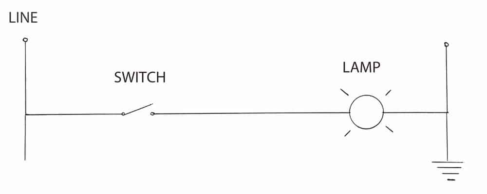
The most generic ladder diagram is shown in Figure 1. The input device is a simple single-pole, single-throw switch. The output device, for purpose of illustration, is a low-ampere power light of appropriate voltage. In this example, the control circuit is powered by 120 V derived from a single-phase service.
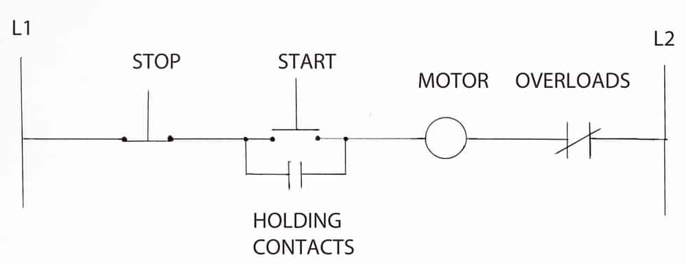
Figure 2 shows a very common setup. A start/stop station, which may be remote from the controller, permits the operator to start or stop a motor. The stop button is normally closed, and the start button is normally open, meaning that is the status of each device when not acted upon. When the stop button is pressed, the current to the motor relay is interrupted, and the motor stops. At the same time, the holding contacts open and remain open until the start button is pressed again. For this reason, the motor remains stopped even when the stop button is released. For simplicity, it is customary to show the control circuit going to the motor without the motor relay or power (which may be three-phase) connected to the relay and feeding the motor.
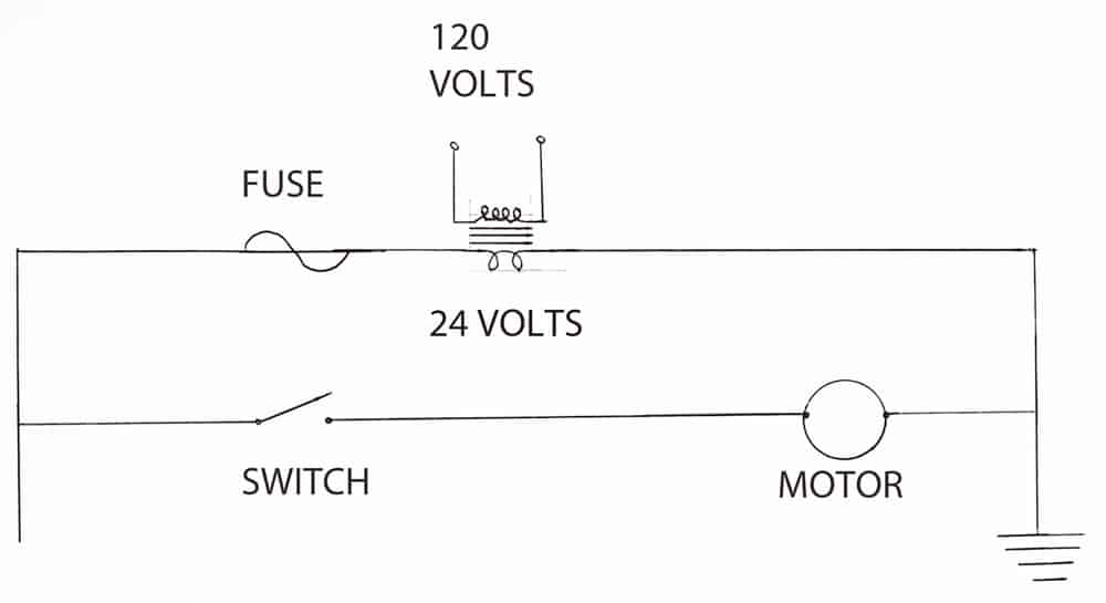
Figure 3 shows another common setup with a 24-V control circuit terminating at a motor. Here, again, the relay and main power supply connected to the relay (and, thence, to the motor) are not shown.
Conclusion
This article has surveyed some relatively elementary motor controllers. The basic principles are the same, but the size and complexity of this equipment increases greatly as more functionality is required. Elevator motion controllers, PLCs and variable-frequency drives (ELEVATOR WORLD, February 2014), often in combination, require vast amounts of knowledge and expertise to design, install and service when something goes wrong. The schematics are sometimes book length, and it takes a special type of mind to comprehend the details.
Other times, there is a simple solution. When the equipment fails to operate, first verify the power connections, then the control wiring and the sensors. For an elevator motion controller, look at the alphanumeric readout. If there is a seemingly cryptic error code (such as “E-8”), go to the manufacturer’s documentation to find out what is happening. Look at the sensors — a very common problem is within a door sensor. Because there are heavy moving parts, along with sensitive electronics, this vital safety device may go down. Check input power, condition of the relay and power at the motor. Check power quality at the motor with an oscilloscope. A multimeter in the “AC volts” function will reveal unwanted ripple in a VFD’s DC bus.
Do not work “over your head” — beyond your body of knowledge. Wires inadvertently reconnected to the wrong terminals in an elevator motion controller have been known to defeat the door interlock, resulting in fatality.

Figure 1: The most basic ladder diagram 
Figure 2: A ladder diagram showing a common configuration
Get more of Elevator World. Sign up for our free e-newsletter.


