MRL Lift Design and Development
Aug 1, 2020

A firsthand account of the origins of the modern MRL
A technology breakthrough was announced in 1996: a way to locate a gearless permanent-magnet (PM) motor directly in the shaft to eliminate the machine room. Though the PM motor were to be small, it would produce high torque to directly drive the car and counterweight in an RPM range of one to 1,000 (versus traditional inductive-motor RPMs of one to 100). To obtain as great a driving force (torque divided by radius) as possible, the radius of the driving sheave would be as small as possible, and the ratio of the roping would be as large as possible, such as 2:1 or 4:1.
Background
Your author has studied machine-room-less (MRL) lift technology since joining Quality Lift Products Ltd. (QLP) as a product-development engineer in 2003. The company had supplied MRL lifts to the U.K. market since 2002. With 1:1 cantilever roping, the design was expensive and poorly engineered; nor was it good for capacity above 1000 kg, as all the loads were taken by one wall on one side of the shaft. In developing future products for QLP, I tried very hard to change the roping to 2:1.
In 2004, I got a chance to do the conceptual MRL lift design for the London Underground (LU) project engaged by what this article will call “Company A,” which would install approximately 120 lifts for the 2012 Olympic Games. I submitted two 3D conceptual models to Company A and LU, and one was accepted. The competitor in the project will be called
“Company B.” This company had already been the supplier of all electric equipment for that project. My design ultimately helped QLP to be the supplier, providing all mechanical equipment.
The reasons why LU wanted tailor-made MRL lifts are:
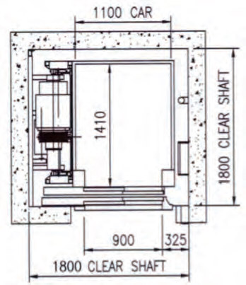
- These MRL lifts had to have through entrances, while most of the existing shafts in LU stations were wide but shallow (in depth). A typical MRL lift with through entrances was not possible to fit in the shafts, as the machine is mounted on one of the car guide rails, and the counterweight is accommodated at the side of the shaft and offsets the car guide rail, which requires greater shaft depth.
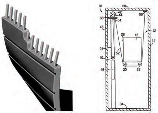
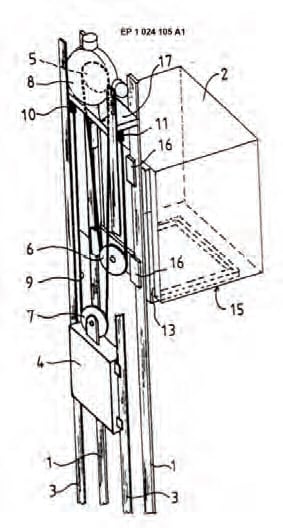
- MRL lifts from some manufacturers used belts to drive the lift car, which was not a good solution for the Tube stations. As the belts were new products at the time, their reliability was yet to be tested by the market (Figure 2).
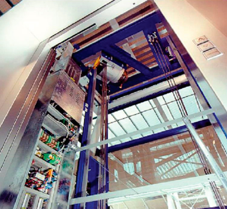
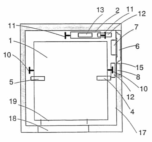
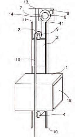
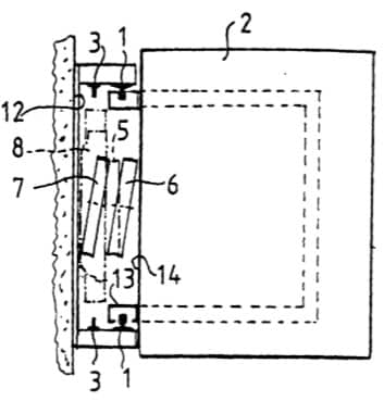
- At the time, one manufacturer had MRL lifts with motor placement directly above the car roof, which required more headroom (Figure 3). (The company’s current global MRL lift has been in production since 2005, but it was launched in the U.K. market in 2007-2008. The design was similar to mine, which I did at least one year earlier, and the capacity of my design is greater than the company’s lifts, which have a maximum capacity of 1000 kg.)
- Standard MRL lifts from other European suppliers were light duty and not suitable for public transportation.
- LU wanted the lifts to be able to be maintained by any independent British lift service company, so they preferred an independent manufacturer. This was especially true for the electrical equipment.
Company A employed QLP to design the MRL lift so that it would not use competitors’ products and not get involved in patent issues.
Critical Components
A neodymium magnet is a rare-earth PM made from an alloy of neodymium, iron and boron to form the Nd2Fe14B tetragonal crystalline structure. This material currently comprises the strongest type of PM (ELEVATOR WORLD, April 2019).
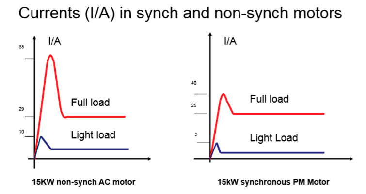
A synchronous electric motor is an AC motor distinguished by a rotor spinning with coils passing magnets at the same rate as the alternating current (AC) and resulting magnetic field that drives it. Another way of saying this is that it has zero slip under usual operating conditions. (Contrast this with an induction motor, which must slip to produce torque.) They operate synchronously with line frequency. As with squirrel-cage induction motors, speed is determined by the number of pairs of poles and the line frequency. Synchronous motors are available from sub-fractional, self-excited sizes to high-horsepower, direct-current-excited industrial sizes. In the fractional horsepower range, most synchronous motors are used where precise constant speed is required. In high-horsepower industrial sizes, the synchronous motor provides two important functions. First, it is a highly efficient means of converting AC energy to work. Second, it can operate at leading or unity power factor and thereby provide power-factor correction.
PM Motor Characteristics
T = BLR2πRA = 2BA(πR²L)= 2BAV (1) where T = torque (total), B = magnetic field strength, L = conductor length in the magnetic field, R = equivalent radius of the motor, and V = motor volume (motor equivalent section of X length).
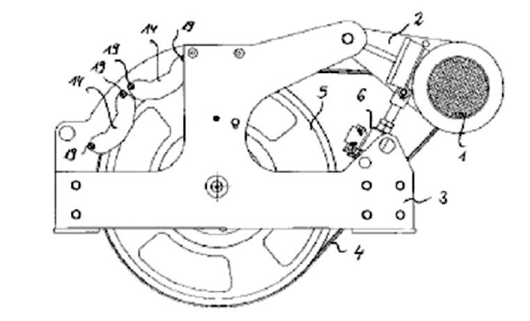
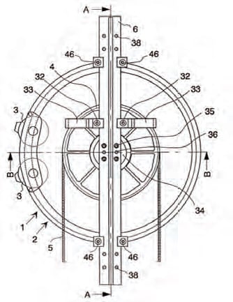
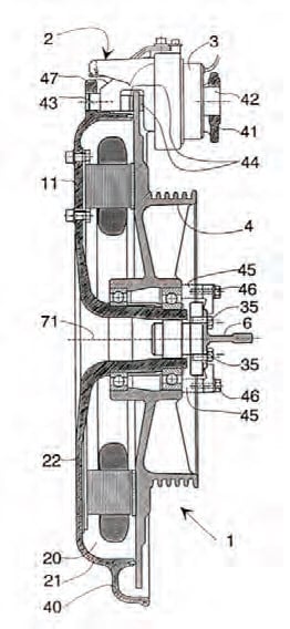
Due to magnetic saturation, magnetic field strength cannot be increased infinitely. To increase torque, only two ways are available: increasing the motor’s diameter and/or increasing the motor’s length. That is why PM motors are usually made flat (skinny but with large diameter) to obtain the highest possible torque. Another purpose of a large-diameter rotator is to obtain a larger ratio between the rotator and driving sheave. Figure 4 shows a similar concept to increase the torque without using a gearbox. As the torque is proportional to the square of the radius, it is imperative to begin with a (flat) PM motor when designing MRL Lifts.
Relationship Between D/d and Rope Life
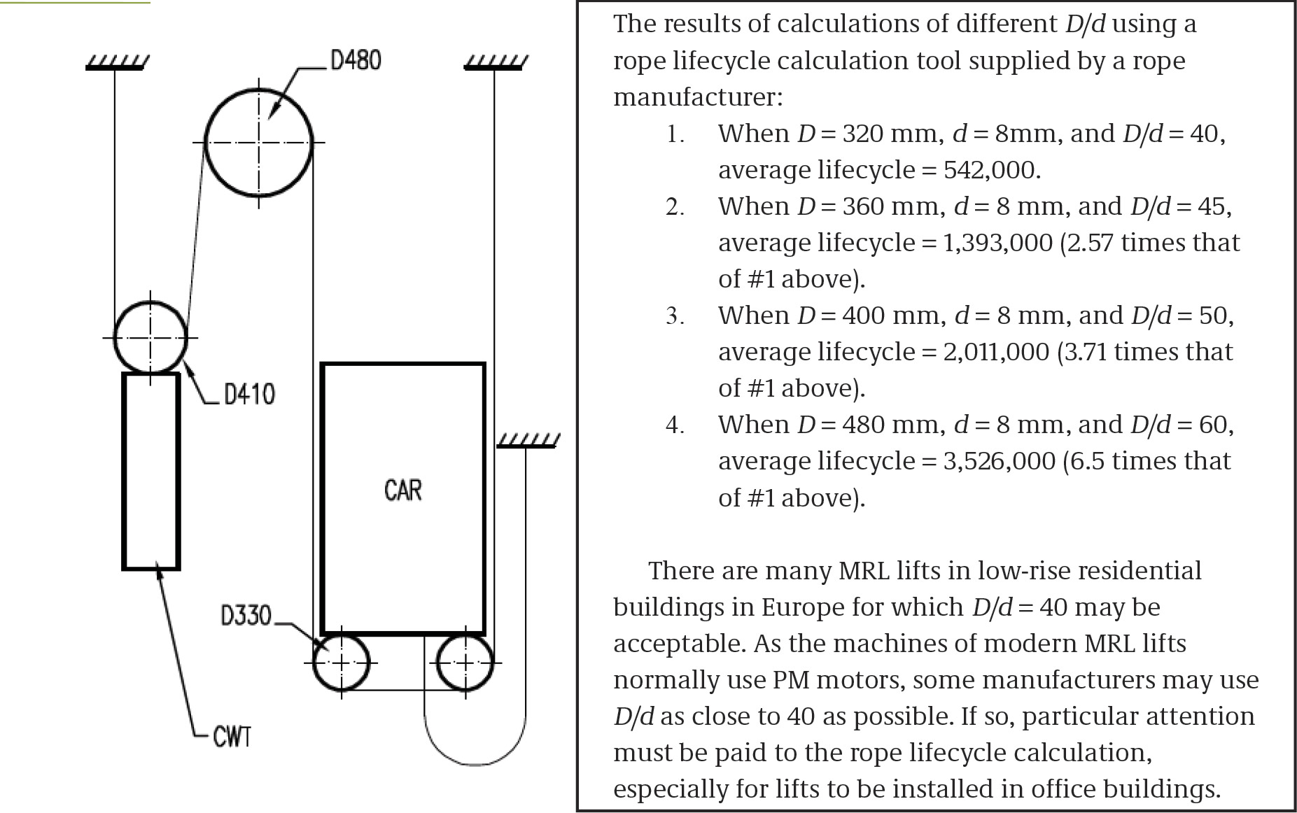
F = T/R where F = driving force, T = torque, and R = radius. One way to have enough F under a constant motor rotary speed is to make the radius of the driving sheave as small as possible. However, the sheave diameter must be greater than 40 times the rope diameter. Normally, in MRL lift design, the rope diameter (d) selected is 8 mm (more specifically, 7.92 mm). The sheave diameter (D) is 40 X d = 320 mm. If the rope diameter is too small, it will need too many ropes when under load. With a pencil-style PM motor, D has to be as small as possible, which is why some MRL manufacturers have to use the belts, instead of ropes, to drive the lift car and counterweight. It is important to note that D/d should be at least 45; otherwise, the ropes will wear very quickly — possibly reduced to less than two years for a very busy lift.
Ideal Speed and Effectiveness
As most PM motors are designed for 2:1 roping, assume the speed of a lift (V) as 1 m/s, and d = 320 mm. Then, rotary speed for 2:1 roping would be 240 rpm. If the roping is 1:1, the speed is half that of 2:1 roping. PM motors have wide speed ranges; ideal rotary speed may be 400 rpm (for 1.6 m/s speed) or higher.
PM motor effectiveness at low speed cannot be very high (should be less than 83%). Some product advertisements claimed effectiveness greater than 95% — that is at ideal speed. For example, at 1.6 m/s, with 2:1 roping, the required ideal speed is 400 rpm). At lower speeds, such as 1 m/s, the lost energy will be converted into heat. As the rare earth magnet is rather sensitive to overheating, the motor is prevented from working very frequently (e.g., as it would in a high rise). If the motor overheats, when temperature is greater than 150°C, it may temporarily lose magnetism; if it overheats too seriously (e.g., at 370-400°C/short circuits), it may permanently lose magnetism. This is why most PM motor installations must include ventilation fans.
Acceleration
Without a gearbox — which is a torque amplifier, rather than a speed reducer — the PM motor’s acceleration factor is much lower than that of a geared machine, which is normally a = 0.5 m/s². When your author designed the two-floors MRL lifts for a project, the client initially specified 1.6 m/s speed. I did a calculation and showed the results to the client to prove that 2.56 m is the minimum distance to get to the full speed (V = a X T, T = V/a = 1.6/0.5 = 3.2 s, H = 0.5 X a X T² = 2.56 m). If the floor height is shorter than 5.12 m (2.56 m X 2), the car will never reach full speed. This higher speed could only save a few seconds over a speed of 1 m/s, yet require the whole system to be designed to suit the higher speed. This would increase the total cost by at least 40%. Furthermore, as the PM motor would mostly work at a speed below 1.6 m/s, energy effectiveness would be poor.
Car Weight
When a torque is applied to a body, the angular acceleration ( ) is given by = /I. depends not only on the torque ( ), but also on the moment of inertia (I) of the body about the given axis, which is determined by using the equation. When is fixed, to have greater acceleration, the moment of inertia of the driving-wheel assembly must be kept as small as possible. As a result, the MRL lift car should be lightweight (e.g., for a typical MRL lift with a capacity of 1000 kg, the car weight should be 790-1,150 kg). Sometimes, even aluminium cars are used to reduce their weight for reasonable acceleration.
Roping Ratio
Most MRL lifts use 2:1 roping. Benefits are:
- To reduce the number of ropes by half
- To easily increase the torque by twice at starting and low speeds
- A 50% reduction in size with the same lifting capacity
- A 1:1 motor is more than 40% more expensive than a 2:1 motor.
- 1:1 roping is not economical for capacities greater than 630 kg.
Speed
PM motors have a wide variable speed range, so the rated power should also be variable. It would be OK to use the same type of PM motors for lifts at different speeds. For example, the same PM motor could be used for MRL lift configurations of 630 kg at 1 m/s and 630 kg at 1.6 m/s.
Integrated Lift Car With Underslung Diverters
New car design concepts for MRL lifts include building the car sling with car panels together with underslung diverters to have less on the cartop. Note that a 700-mm cartop balustrade is required when the gap between the car panel and side wall is less than 500 mm; if the gap is greater than 500 mm, the balustrade height must be 1,100 mm.
High-Speed MRL Lifts
MRL lifts are not suitable for high-rise buildings. First, as the roping ratio is 2:1, when the rated speed is greater than 3 m/s, rope speed will be greater than 6 m/s, which is too fast for the whole system. Second, due to the length of ropes and compensation chain/ropes, the mass of the whole driving sheave assembly is much bigger than low-speed MRL lifts. To have acceptable acceleration, the PM motor would have to be very large. As a result, the lift shaft would not be able to accommodate the machine.
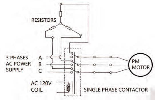
MRL Lift UCM Protection
PMs are installed in the rotors of PM motors to provide a permanent magnetic field, so it is not necessary to induce high current rotor for the motor to run. If connecting the main contactors normally closed terminals to a set of resistors, if the brakes fail when the car and counterweight are not in balance, the PM motor becomes an AC generator. In this case, the electric currents are exhausted by the resistors. While they cannot fully stop the movement, they produce a resistant torque against it to considerably slow it. This effect can be regarded as unintended car movement (UCM) protection when the brakes fail or under a misoperation (e.g., a real accident in which a service engineer remotely released the brakes, which resulted in the lift car crashing into the headroom, seriously damaging the lift car and counterweight buffer).
Patents
Criteria for patents in the U.K. are that the idea must not be previously disclosed, must have an inventive step and must be an industrial application. These have a 20-year lifespan. As rules can be complicated and vary from country to country, those seeking them should get professional advice (e.g., a patent agent). Abstract concepts such as the following are not patentable in the U.K.:
- Scientific theories
- Presentations of information
- Computer programs
- Methods of diagnosis
Your author joined Company B in June 2008. I was required to produce manufacturing drawings for an 800-kg MRL lift, which was based on an existing 630-kg MRL lift design in 2D with 1:1 roping. I took this chance to convert the 630-kg lift from 2D drawings to a 3D model. I was able to do this over only the course of a month, as I fully understood the principle of the previous design. Additionally, I found that the following objectives could be achieved:
- Improvements in safety
- Headroom reduction of 700 mm
- Fewer ropes and half the forces loaded on the gear/diverter wheels
- Reductions in materials and manufacturing costs
Major Challenges Faced
Most lift components are made from sheet-metal with a minimum tolerance of ±0.5 mm. As the lift is installed in a shaft with a tolerance of ±25 mm, the components are easy to design and manufacture. Regarding engineering principle, your author mainly followed EN 81-1 Safety Rules for Construction and Installation of Lifts. The new lift must be 2:1, as many layouts with 2:1 roping had been registered as patents in Europe. Therefore, avoidance of infringing upon the patents was your author’s greatest challenge.
Process and Investigation
Your author’s 3D model enabled all problems in the existing design to be found very quickly. Not only did the design have safety issues, it also required 700 mm more headroom than most other makes. Most existing lift shafts had limited headrooms (approximately 2,800-3,500 mm), which is why MRL lifts have been in great demand for full replacement of lifts in existing buildings.
Top Clearance
Assuming the distance between the counterweight and its buffers is 200 mm, and compression is 170 mm (as minimum), four conditions must be satisfied when the counterweight rests on its fully compressed buffers:
- The guided travel of the car, still possible in the upward direction, must be equal to or greater than the minimum travel, given by the formula 0.1 + 0.035V²(m), where V is the rated speed (m/s).
The free height above the roof of the car enclosure must be at least 1 + 0.035V² (m). - The free distance between the lowest part of the ceiling of the hoistway and the highest part of the guide shoes of rope attachments and any part of a vertical sliding door must be at least 0.1 + 0.035V²(m). Also, the distance between the lowest part of the ceiling and the highest part of any other equipment fixed on the car roof must be at least 0.3 + 0.035V² (m).
- There should be sufficient space above the car to accommodate a prism block with minimum dimensions 0.5 X 0.6 X 0.8 m resting on one of its faces. With direct-roping elevators, the suspension ropes and their attachments may be included in this space, provided that the distance between the rope centerline and at least one vertical face of the block does not exceed 150 mm.
- Similarly, when the car rests on its full compressed buffers, the guided travel of the counterweight, which is still possible in the upward direction, must be at least 0.1 + 0.035V²(m).
Pit Depth
Assuming the distance between car and its buffers is 50 mm, and compression is 170 mm (as minimum), the following conditions must be satisfied when the car rests on its fully compressed buffers:
- There must be sufficient space in the pit to accommodate a prism block of the dimensions with minimum dimensions 0.5 X 0.6 X 0.8 m resting on one of its faces.
- The clear distance between the bottom of the pit and (a) the lowest part of the guide shoes, safety-gear blocks, toe guides or any part of the vertical sliding doors must be at least 0.1 m. (b) The lowest part of the car, except for items detailed in (a), must be at least 0.5 m.
- The free vertical distance between the top of the components fixed in the pit, such as a tensioning device for compensation ropes, and the lowest part of the car, except for components detailed in (a) (one bullet above) must be at least 0.3 m.
| Existing Design (1:1) | New Design (2:1) | |
| Minimum Headroom | 4.36 m (minimum) | 3.69 m |
| Minimum Pit | 1.557 m | 1.557 m |
| Number of Ropes | 8-10 | 4-5 |
| Size of Motor | A | 60% of A |
| Motor Cost | B | 60% of B |
| Forces and Loads on Gears | C | 50% of C |
Expected Outcomes
Other Models
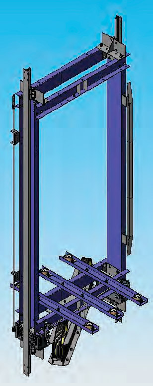
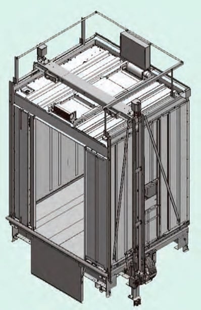
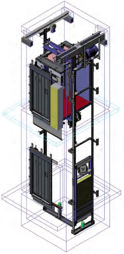
Your author also produced two other models for Company B, which were similar to the lift I designed for the LU project in 2004. (I also saw a similar design in Sydney, Australia, in January 2020). Since these were not adopted, they are allowed to be published as my personal exercises (Figures 16 and 17).
Lessons
Your author learned many solutions for MRL lift design when working at a multinational corporation. This design can be extrapolated in the following ways:
- The diverter wheels can be hung underneath the supporting beams.
- The car-sling height can be further reduced by 200 mm; minimum headroom can be changed to 3,500 mm.
- Pit depth can be reduced to 1.350 m.
- D/d should be at least 45.
Contributions to the Project
Your author did the following in working on the project:
- Overruled the existing design, which had many concealed safety problems
- Considerably reduced costs and manufacturing complexity
- Set up a powerful 3D computer-aided-design system for the company
- Improved design capability from bespoke MRL lifts having a maximum capacity of 800 kg to a whole series of lifts with higher maximum capacities ready for mass-manufacturing.
Conclusions
The following conclusions can be drawn:
- MRL lift design is based on the PM motor; it is imperative to select the right one. The motor serves as the first consideration in the design.
- The size of the PM motor is determined by applied torque, rather than power.
- A roping ratio of 2:1 is always better than 1:1.
- Compared to a pencil-style conventional PM motor, a disc/flat PM motor is always the first choice for MRL lift design.
- Top drive is always better than bottom drive: the ropes in a bottom-drive system are required to be too long with too many diverters, which considerably shorten rope life.
- 3 m/s should be the maximum speed for an MRL lift; otherwise, the rope speed is too fast.
- Maximum travel height for an MRL lift should be less than 120 m; otherwise, the PM motor can easily overheat due to frequent stops/starts. Orders for lifts that must run for a long time should not be filled with MRL lifts when total travel exceeds 100 m.
- The MRL lift is a light-duty product and should not be recommended for heavy-duty purposes, such as for public housing, multistory parking garages or railway stations. If there is a special need, higher-power-rated MRL units should be employed so more car weight can be allowed, making the lift car more robust (e.g., an 800-kg-capacity standard MRL lift modified as a 630-kg-capacity MRL lift with a heavy, robust car).
- The MRL lift was first launched in 1996. These patents should have expired by end of 2016, so some ideas of MRL lift design can be used for any project. Should usage questions arise, it is recommended to consult a patent agent to confirm.
- Nowadays, PM motors, instead of AC geared machines or DC gearless machines, are widely used in machine-room-above lifts. As I have experienced some tender submissions that used MRL lift solutions for machine-room-above lifts to reduce cost to a minimum, particular attention must be paid to those “small machine room” lifts for mid-rise buildings. Simply moving the machine of an MRL lift out of the shaft to the machine room to build a machine-room-above lift is not acceptable, especially for office buildings, for which the roping ratio of the machine-room-above lifts should be 1:1, rather than 2:1. This is because a machine-room-above lift machine would have larger tolerance, better reliability and longer rope lifespan at 1:1, as opposed to 2:1.
Standards Compliance
The top clearance and the pit depth in this article was compliant with EN81-1:1998 (as the design was done in 2004-2009).
References
[1] Peizhong Ma. “The Key Solution of MRL Design,” China Elevator, 2002, 13(5): p. 7-10.
[2] Lubomir Janovsky. Elevator Mechanical Design, 3rd Edition.
[3] European MRL lift patents

Get more of Elevator World. Sign up for our free e-newsletter.


