New Electrical Test Instruments for Elevator Work
Feb 1, 2020
Several products to make the lives of elevator designers, installers and maintainers easier and safer, and how to use them
by David Herres
In elevator diagnosis and repair, much more than half the work is electrical. This is not to say that the mechanical and structural components are less important, but the flow of electrons starts and stops the car; opens and closes doors; and enables the sensors and actuators, together with safety interlocks, to work seamlessly. Additionally, the power flow to motor and brakes is a critical part of the picture. These elements interact with other building services (fire alarms and sprinklers) and, typically, with redundant phone links to emergency facilities outside the building.
In most instances, when onsite electricians and personnel or outside elevator technicians are summoned, they are confronted with a less-than- catastrophic event that can be quickly resolved. An example is hoistway doors that need to be checked to see if one of them is not seated firmly in the closed position. Another example is that the motion controller must be reset. This, however, may be problematic. A reset is often the quick and easy solution, but it does not address the underlying issue. On the other hand, when a car full of passengers is stuck between two floors, there can be health and safety considerations, which most experienced technicians realize and weigh heavily in decision making.
This article assumes a passenger extraction has been performed, if necessary, and that the situation has been stabilized so there is no threat to either safety or the integrity of the elevator system. It is now that the electrical test equipment will be used. Traditionally, volts, amps and ohms were measured by a single instrument — the multimeter, which is still essential, despite the emergence of imaging equipment. Currently, in the shop or lab, a bench-type multimeter is common due to its many advanced features.
| Learning Objectives |
| After reading this article, you should have learned about: ♦ Unique features in a bench-type multimeter ♦ Instrument features needed to perform work on elevators ♦ Voltage limits in multimeters ♦ Noncontact voltmeters ♦ New, safer electrical hand tools |
Background
During a lecture in 1820, Hans Christian Ørsted was surprised to see that a compass needle deflected from its alignment with the earth’s magnetic North Pole when a conductor carrying electric current was brought near.
Entrepreneurs commenced building and marketing instruments based on this principle. They measured amps, and by reconfiguring the circuit and recalibrating the dial, the instrument could measure volts. From this, it was a simple step to measure resistance and with added switches, creating the multimeter, which began to appear in labs and factories.
The Fluke 8808A
The Fluke 8808A digital bench-type multimeter has numerous features not available in the typical handheld instrument. On the front panel is a dual-vacuum fluorescent 5-1/2-digit display. It is clear and very readable. Two properties of a signal at the input can be read simultaneously: for example, frequency in Hertz and current in amps. In ohms mode, optional dual probes, essential for precise low-resistance readings, can perform four-wire measurements. In volts mode, the safe DC range is 200 mV to 1,000 V, and AC readings can be taken from 200 mV to 750 V, both with 1 µV sensitivity. This means the instrument is suitable for working on 480-V, three-phase variable-frequency drives. These are widely used, in conjunction with induction motors, to power elevators. When measuring resistance, the range is 200 ohms to 100 megohms, with 1 milliohm sensitivity. Lower resistance values can be measured by inserting a series resistor. When measuring current, the DC range is 200 µA to 10 A with 1 nA sensitivity. Frequency measurements can be made from 20 Hz to 1 MHz.
The 8808A can perform continuity and diode tests. Measurement rates can be set at 2.5, 20 and 100 samples per second. A compare mode is available to determine if a measurement is within specified limits. An RS-232 interface enables remote operation. Meter calibration can be performed without opening the enclosure.
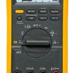
The Fluke 87V
The new Fluke 87V handheld, battery-operated multimeter can easily be recognized by its prominent yellow button to the left, just under the display. At under US$430, it is a great industrial multimeter and quite suitable for elevator work. The product is optimized for servicing inverters and variable-frequency drives (VFDs). This is particularly useful in diagnosing elevator motor problems. The control signal from the motion controller is typically a pulse-width-modulated quasi- square wave with very fast rise and fall times. The accompanying high-amplitude harmonics can mislead the auto-ranging function of a conventional multimeter, obscuring the actual signal of interest. Pressing the yellow button temporarily diverts the signal through a built-in low-pass filter so these harmonics are not displayed in the meter’s readout.
In low-pass mode, the 87V enters manual mode. The user then selects the desired range by pressing “Range.” All of this is relevant for measuring the VFD inverter input and output, which are critical for elevator motor performance. Voltage limits are 600 VAC and 1,000 VDC, so this instrument is suitable for work on three-phase, 480-V VFDs frequently used to power elevator motors. The meter is insulated from the system ground and has isolated inputs, so it is safe to measure voltages that are referenced to but float above ground, as well as three-phase supply voltages and the higher DC bus voltage.
Another valuable feature for elevator work is the meter’s ability to measure temperature. A type-K thermocouple probe is included. Especially of help in elevator maintenance, it enables the user to quickly check Celsius or Fahrenheit temperatures at specific locations. For example, front and rear motor-bearing temperatures can be measured and compared. Also, termination and semiconductor temperatures can be checked to locate a problem or as a routine maintenance procedure.
The continuity test is a valuable capability. With power off and residual voltages eliminated, press the continuity button to turn it on. The continuity function detects opens and shorts as brief as 1 ms. An audible beep sounds when low ohms indicates a short-circuit.
Other than voltage, the most-used function is resistance. Here again, the equipment should be powered down, and residual voltages, as in electrolytic capacitors, should be bled out. Do not shunt them with a screwdriver! The abrupt transition damages electrolytic capacitors and semiconductors. Instead, use a power resistor with alligator clips attached to leads and do a volts measurement to verify.
Remember that the measured value of a resistor is often different from the resistor’s nominal value. This is partly because the resistor may have a tolerance as high as 20% — as indicated by the last band in the color code — and partly due to the introduction of parallel resistance in the associated circuitry, which can be eliminated by temporarily cutting one of the resistor leads.
The following is a way to avoid the inherent uncertainty in low-resistance readings. Since conductance is the reciprocal of resistance, high values of conductance correspond to low values of resistance. The 87V’s 60-nS range measures conductance in nanosiemens, a range that permits the user to measure the resistance of components up to 100,000 megohms (well outside the range of a conventional multimeter) with very accurate low-resistance readings. To measure conductance in ohms mode, repeatedly press “Range” until nS appears in the readout.
Electrical noise may be present in high-resistance readings. You can smooth out a noisy reading by entering the “MIN MAX” recording mode. Then, proceed to the “Average” reading. With test leads open, there is a residual conductance reading. Use the “Relative” mode to subtract the residual value.
The 87V can be used to check a capacitor, which can be done with a conventional multimeter in a roundabout way by watching the capacitor’s charge/discharge cycle. However, the 87V can measure actual capacitance, either in a component or in a circuit, as follows. Use the rotary knob to choose “Diode Test.” If the diode is in a circuit, the equipment must be powered down and residual voltage removed. The diode test can also check transistors, silicon-controlled rectifiers and other semiconductors. The meter sends current through the NP/PN junction and measures the voltage drop. In a silicon-based device, a measurement of 0.5 to 0.8 V indicates the component is good.
To test a diode out of circuit, connect the red lead to the positive terminal and the black lead to the negative terminal. In a circuit, a good forward-biased diode will read 0.5 to 0.8 V. The reverse-bias reading will vary depending upon the resistance of associated circuitry. A short beep sounds if the diode is good. A continuous beep indicates the component is shorted. If it is open, the display reads “OL.”
Measuring current with any multimeter is problematic. Many cautions must be observed. Consider that, in volts mode, the meter is a high-impedance load. The probes can be safely connected across any voltage source or load, provided the rated voltage of the instrument is not exceeded. A minute amount of current flows through the instrument.
In current mode, the situation is totally different. The meter is a low-impedance load, and the full amount of current flows through it. Depending upon the amount of current being measured, the circuit and instrument may be damaged. The meter is fuse-protected, but if the current is beyond the capability of the fuse, there can be material damage and even a hazardous arc blast. It should be observed that the maximum current rating of the 87V is 10 A.
Another way current measurements are problematic with any multimeter is the fact that the instrument must be placed in series (not in parallel, as in a voltage measurement) with the component or circuit being measured. If there is a nearby screw terminal, you’re in luck, but the current measurement usually requires cutting one of the leads and later re-soldering it, which is quite difficult on a printed circuit board. But, as we shall see when we examine two recent Fluke instruments, there is a way out of these difficulties.
The Fluke T6-1000
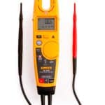
The first is a noncontact multimeter that measures volts and amps in a single readout. It is the Fluke T6-1000 Electrical Tester, far safer and more efficient than conventional multimeters.
According to the manufacturer’s specifications, the T6-1000 is rated to measure 1,000 V, AC or DC, and 200 A in current mode. It is safe for 1,000 V in a CAT III location and 600 V in CAT IV, where there is greater available current. It is suitable for three-phase, 480-V work, including the 678-VDC bus seen in VFDs for high-horsepower motors. The open-fork design accommodates a 4/0 conductor, as used in a 200-A electrical service.
The T6-1000 electrical tester resembles a clamp-on ammeter but operates quite differently. The clamp-on ammeter performs current readings by detecting the magnetic field surrounding a conductor through which current is flowing. The jaws close around the conductor, enabling current to flow through the instrument’s secondary coil.
The T6-1000, in contrast, capacitively senses the electrical field surrounding an energized wire even when there is no load or current flowing. Neither meter can read anything in a cable such as Romex, or a flexible cord that contains a hot wire and neutral return conductor, or two or more opposing phase wires, because the current and/or voltage (and, consequently, magnetic or electrostatic fields) cancel out and give a zero reading.
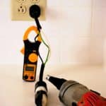
The good news is that you can make a splitter in a method that works for both the clamp-on ammeter and T6-1000. Slit and remove a few inches of outer jacket and separate the white and black or phase wires. You may want to determine how much current a cord-and-plug- connected motor or appliance is drawing. This field-made splitter can make that possible.
For noncontact voltage, current and frequency measurements, clip the black lead firmly in place. The wire must be set against the bottom center of the jaws to take a reading. Then, before taking a reading, place your finger against the spot indicated on the back of the meter. This provides a capacitive path to ground potential so the meter can sense the electrostatic field. Turn the rotary knob to select “Field Sense.” The readout will become green when it is ready to measure the electric field. The Fluke noncontact electrical tester also works as a conventional multimeter. Use the leads to make ordinary voltage and resistance measurements. The resistance mode has an audible continuity indicator. The T6-1000 does not require contact with a live conductor, so the technician should never be exposed to hazardous voltage.
The Fluke Model 325
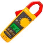
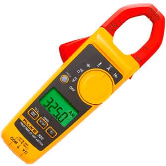
Another noncontact test instrument is the Fluke Model 325 Clamp Meter. Clamp-on ammeters have been around for years, but this digital meter has many added features. It is also a multimeter with the ability to read volts; ohms; capacitance; frequency; and with the included specialized probe, temperature.
A conventional ammeter must be placed in series with the load to read current. All the current passes through the meter. This contrasts with the voltmeter, which is placed in parallel to the load and/or power source. In taking voltage readings, only a small amount of current passes through the instrument.
To review, there are two disadvantages to the conventional ammeter. First, the circuit must be temporarily cut open (and later reconnected) to make the measurement. Second, this approach will only work for low-current electronic circuits, not for any kind of motor work. The clamp-on ammeter solves both these problems. Simply open the jaws and insert the live conductor. As always, current passing through it creates a magnetic field, and corresponding current is induced in a winding in the jaws. This is displayed in the calibrated, auto-ranging readout. The conductor need not be centered in the jaws. If it is more to one side, the magnetic field is stronger there and weaker on the other side, so the average is the same. This can be verified by moving the conductor during a measurement. The readout in amps will remain stable. Similarly, it does not matter if the conductor passes through at an angle (often the case when working inside a small enclosure).
The 325 can read up to 400 A, which makes it useful in large motor work. It will measure DC amps, switching over to “Hall Effect” mode, and conductors need not be insulated. If the amount of current is too low to be read, loop the conductor a few times around one of the jaws to multiply the current by that number. Then, divide the number that appears in the readout by the number of turns needed to get back to the correct value.
The 325 includes probes that plug into the bottom so the instrument can be used as a multimeter. For example, in ohms mode, it incorporates an audible continuity checker, indicating if the resistance is less than 30 ohms. With the included temperature probe, a button on the front panel toggles between Celsius and Fahrenheit. On the front panel are “Hold,” “MIN MAX” and “AC/DC” buttons and a separate button that illuminates the readout for low-light conditions. Use this only when needed, to save on the battery, (two AAAs).
AC and DC voltage limits are 600 V with 0.1-V resolution, so the meter is good for general 480-V three-phase work and is useful for the 480-V VFD. Voltage on a 480-V VFD DC bus is 678 V. This 678-VDC bus comes out of the full-wave rectifier and is based on AC peak-to-peak voltage.
The Fluke ScopeMeter
The instruments outlined so far are designed to display numerical values in digital readouts, and they do that in a very clear and user-friendly way. But, in the course of elevator product development and diagnosis in existing installations, there comes a time when engineers and technicians need to visualize the electrical waveforms to understand what is going on in the circuitry. This is true in looking at three-phase power quality at the VFD supply. Additionally, it is necessary to check the internal DC bus to make sure the voltage is free of AC ripple. Then, at a much lower voltage level, the inverter input can be checked to make sure digital signals are accurate with proper thresholds and timing free of jitter. Finally, high-voltage pulse-width-modulated power at the motor terminals should be accurate and free of noise.
A bench-type oscilloscope is not a good choice to display these signals due to the hazard of voltages that float above but are referenced to the electrical ground. An improper hookup using a bench-type oscilloscope can result in a powerful arc fault that will damage the oscilloscope and VFD, and possibly injure the user. For this work, a handheld, battery-powered oscilloscope with inputs insulated from ground and from each other is generally used. This instrument has the further advantage of rugged construction, making it suitable for use outside the lab or shop.
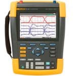
An excellent instrument for this purpose is the Fluke ScopeMeter (ELEVATOR WORLD, December 2018). The instrument has separate oscilloscope and multimeter probes and inputs. In addition to displaying the signal, a very clear readout shows volts, amps, ohms and frequency, making the ScopeMeter a capable all-purpose instrument. It is light, portable and quite safe to use on three-phase, 480-V systems.
Other Fluke Tools
Fluke is offering a new line of electricians’ hand tools. They are rated safe for 1500 VDC, but Fluke has tested them at 10,000 V. A few are illustrated here. They can be purchased individually, in groups or as a complete set. They are manufactured in Germany and carry a lifetime warranty.
| Learning-Reinforcement Questions |
| ♦ Use the below learning-reinforcement questions to study for the Continuing Education Assessment Exam available online at www.elevatorbooks.com or on p. 117 of this issue. ♦ Why is there a problem in resetting the motion controller before determining the cause of an elevator outage? ♦ What was Hans Christian Ørsted’s discovery? ♦ What are the advantages of noncontact meters? ♦ How does a clamp-on ammeter sense current? ♦ How does the Fluke T6-1000 Electrical Tester sense voltage? |
- The Fluke 87V handheld,battery-operated multimeter
- The Fluke T6-1000 Electrical Tester
- Splitter for use with a clamp-on current meter
- The Fluke Model 325 Clamp Meter, which includes a carrying case with belt loop
- The Fluke 190-502 ScopeMeter
- Other Fluke Tools
Get more of Elevator World. Sign up for our free e-newsletter.
