Research on Elevator Control Method
Jun 1, 2012
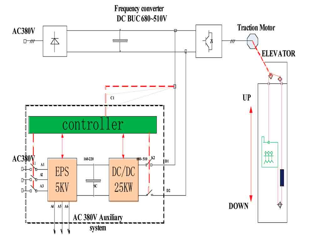
The use of a bidirectional DC/DC converter to control a super-capacitor energy storage device for an elevator is examined.
by Shi Liguang, Yao Lianghong, Luo Zhiqun and Wan Jianru
Elevators have been extensively applied in the rapid development of commercial high rises. As elevator energy consumption is similar to that of air-conditioning systems in the perspective of a whole building’s energy consumption (5-15%), it should take advantage of regenerative energy. This article will focus on the use of a bidirectional DC/DC converter to control a super-capacitor energy storage device according to elevator motoring and regenerative brake and energy-feedback characteristics.
In recent years, the number of elevators in China has increased, and the country’s production of elevators is among the highest in the world. Elevators can potentially save much energy by using different drives, especially since super-capacitor energy-storage technology has seen great development due to the common benefits of renewable energy. The elevator’s inverter converts voltage from AC to DC when the elevator is traveling up with a light load, traveling down with an overload or in the process of regenerative braking, which generates renewable energy stored in DC capacitance. However, high pumping voltage produced due to the lack of an accumulator to absorb high capacities of energy is harmful for the DC bus capacitance. This is resolved by installing DC bus braking resistance in the conventional way, in which the accumulated power will be consumed in the form of heat energy.[1]
The traditional control method of increasing energy waste is not in line with energy-saving policies. To solve this problem, this article presents a modified method of transforming the accumulated power in DC capacitance to AC current (which is the same frequency and phase as the grid voltage) and directly feeding it back to the power grid. However, the control method is very complex, and at the same time, the power amplitude varies widely, which has an adverse effect on the safe operation of the power grid during the regenerative-energy feedback process.
In this process, a bidirectional DC/DC converter with a super-capacitor energy-storage device is connected between the rectifier and the inverter, which not only allows elevator feedback energy to be absorbed efficiently, but can also directly supply the elevator and auxiliary devices. The proposed control method can equalize the power and avoid the negative effects generated by energy feedback on the grid. In addition, a super-capacitor energy storage device can also be used as an uninterrupted power supply to make the elevator safely stop near the closest floor in case of sudden power loss. The control method is verified through charge-discharge simulation and applied in sample elevators with speeds of 2 and 4 mps. The results show that elevators with super-capacitor energy storage devices can save significant amounts of energy and operate smoothly.
Structure and Simulation Analysis of the Super-Capacitor Energy Storage Device
The maximum pressure endurance of a single capacitor is very low (1-3 V), and it cannot be directly connected to the DC bus, where the voltage is hundreds of kV. To improve the capacity of storing energy and the ability to withstand voltage, super capacitors can be used in series and parallel. In the process of charging and discharging, super capacitors’ voltage range is very large; thus, a converter with bidirectional energy flow is attached to the DC bus. The power converter works in “Buck” mode in the process of charging and works in “Boost” mode in the process of discharging. The converter cannot only maintain constant DC bus voltage, but also greatly reduce super-capacitor voltage levels in the energy storage device, so it is adapted to energy storage in other working conditions. In light of these characteristics, an un-separated bidirectional DC/DC converter that can realize double-quadrant flowing of the current is adopted in this paper.[2 & 3]
Super-Capacitor Energy Storage Device
In Figure 1, the super-capacitor energy-storage device (within the dotted line) consists of super-capacitor stacks, emergency power (EPS), a bidirectional DC/DC converter and a controller. The device is used along with the frequency converter, where the feedback energy is transported to super-capacitor stacks by the bidirectional DC/DC converter. The stored energy can supply an auxiliary elevator system with EPS and drive a traction machine operating through a bidirectional DC/DC converter.
Super-Capacitor Charge and Discharge Control Strategy
The process of super capacitor charge/discharge is controlled by a bidirectional DC/DC converter (Figure 2), whereas the charge/discharge problem transfers to the control problem. According to the converter’s modes of operation, it uses inductor current as the inner loop and DC bus voltage as the outer loop to control the circuit in Boost circuit mode, while in Buck circuit mode, it uses the inductor’s current as the inner loop and super-capacitor voltage as the outer loop to control the circuit.
Although the bidirectional DC/DC converter is a typical nonlinear system, there is a linear relationship between variables and small circuit disturbances when it works near a stable state. The small signal and dynamic models of Boost and Buck circuits have been studied in detail.[4] However, these are not explored further here due to space constraints.
Simulation and Analysis
The capacity of the super capacitor is 75 F, and the working voltage range is from 175-240 V. Equivalent series resistance is 48 ohms (a single capacitor is 0.3 ohms), and equivalent parallel resistance is 10,000 ohms. In the bidirectional DC/DC converter circuit, inductance is 0.5 mH. DC bus filter capacitance is 0.75 µF in the frequency converter.
Based on the logical analysis of super-capacitor and DC bus voltage, the bidirectional DC/DC converter switches automatically in different working modes. First, the initial super-capacitor voltage is set to 200 V in simulation; the super capacitor supplies for the load, and DC bus voltage remains at 600 V. At 1 s., DC bus voltage is switched for 700 V, the super capacitor is charged, and the charging current is limited at 45 A.
Figures 3-5 show that the super capacitor drives the load to operate in 0-1 s., when DC bus voltage is 600 V. At 2 s., DC bus voltage is 700 V, super-capacitor voltage is greater than 175 V, and the bidirectional DC/DC converter works in Buck mode.
Analysis of Experimental Results
In the experiment, DC bus voltage Vdc is 540 V, switch frequency Ts is 10 kHz, and the power of the elevator machine is 16.3 kW. The results in Figures 6-8 demonstrate DC bus voltage (red), super-capacitor voltage (black) and super capacitor charge/discharge current waveform (blue) under no load, half load and 75% load.
When traveling up with no load, the elevator is in a state of energy feedback, during which the DC capacitor voltage could increase to 680 V (Figure 6). Super capacitors with gradually rising voltage are charged through bidirectional DC/DC converters: the highest voltage will be 190 V, and the charging current is about 40 A. When traveling down with no load, the elevator is driven by super capacitors with constantly decreasing voltage, having a DC bus voltage around 550 V. The working process under 75% load is the same as the one under no load. Under half load, the car is in balance with counterweight suspension, and there is no energy-feedback process. As shown in Figure 7, DC bus voltage is maintained at 550 V and super-capacitor voltage is at 175 V, though the bidirectional DC/DC converter does not work.
Conclusion
This article contributes to solving the changing problem of charge/discharge super-capacitor voltage by adding a bidirectional DC/DC converter. Simulation analyses show that the feedback energy can be controlled effectually by the converter in both charging and discharging. With the super-capacitor energy storage device, elevator drive modes have a significant effect on energy savings; with faster speed, there are additional energy savings. According to the study of super-capacitor energy storage, we applied for two invention patents: the separate and self-charging elevator energy-feedback device, and the elevator drive with super-capacitor energy storage (Figures 9 and 10).
Acknowledgements
This paper is supported by the National Science Foundation of China and Administration of Quality Supervision, Inspection and Quarantine Nonprofit Industry Specialized Research Funding Projects.
to that of air-conditioning systems in the perspective of a whole building’s energy consumption (5-15%), it should take advantage of regenerative energy. This article will focus on the use of a bidirectional DC/DC converter to control a super-capacitor energy storage device according to elevator motoring and regenerative brake and energy-feedback characteristics.
In recent years, the number of elevators in China has increased, and the country’s production of elevators is among the highest in the world. Elevators can potentially save much energy by using different drives, especially since super-capacitor energy-storage technology has seen great development due to the common benefits of renewable energy. The elevator’s inverter converts voltage from AC to DC when the elevator is traveling up with a light load, traveling down with an overload or in the process of regenerative braking, which generates renewable energy stored in DC capacitance. However, high pumping voltage produced due to the lack of an accumulator to absorb high capacities of energy is harmful for the DC bus capacitance. This is resolved by installing DC bus braking resistance in the conventional way, in which the accumulated power will be consumed in the form of heat energy.[1]
The traditional control method of increasing energy waste is not in line with energy-saving policies. To solve this problem, this article presents a modified method of transforming the accumulated power in DC capacitance to AC current (which is the same frequency and phase as the grid voltage) and directly feeding it back to the power grid. However, the control method is very complex, and at the same time, the power amplitude varies widely, which has an adverse effect on the safe operation of the power grid during the regenerative-energy feedback process.
In this process, a bidirectional DC/DC converter with a super-capacitor energy-storage device is connected between the rectifier and the inverter, which not only allows elevator feedback energy to be absorbed efficiently, but can also directly supply the elevator and auxiliary devices. The proposed control method can equalize the power and avoid the negative effects generated by energy feedback on the grid. In addition, a super-capacitor energy storage device can also be used as an uninterrupted power supply to make the elevator safely stop near the closest floor in case of sudden power loss. The control method is verified through charge-discharge simulation and applied in sample elevators with speeds of 2 and 4 mps. The results show that elevators with super-capacitor energy storage devices can save significant amounts of energy and operate smoothly.
Structure and Simulation Analysis of the Super-Capacitor Energy Storage Device
The maximum pressure endurance of a single capacitor is very low (1-3 V), and it cannot be directly connected to the DC bus, where the voltage is hundreds of kV. To improve the capacity of storing energy and the ability to withstand voltage, super capacitors can be used in series and parallel. In the process of charging and discharging, super capacitors’ voltage range is very large; thus, a converter with bidirectional energy flow is attached to the DC bus. The power converter works in “Buck” mode in the process of charging and works in “Boost” mode in the process of discharging. The converter cannot only maintain constant DC bus voltage, but also greatly reduce super-capacitor voltage levels in the energy storage device, so it is adapted to energy storage in other working conditions. In light of these characteristics, an un-separated bidirectional DC/DC converter that can realize double-quadrant flowing of the current is adopted in this paper.[2 & 3]
Super-Capacitor Energy Storage Device
In Figure 1, the super-capacitor energy-storage device (within the dotted line) consists of super-capacitor stacks, emergency power (EPS), a bidirectional DC/DC converter and a controller. The device is used along with the frequency converter, where the feedback energy is transported to super-capacitor stacks by the bidirectional DC/DC converter. The stored energy can supply an auxiliary elevator system with EPS and drive a traction machine operating through a bidirectional DC/DC converter.
Super-Capacitor Charge and Discharge Control Strategy
The process of super capacitor charge/discharge is controlled by a bidirectional DC/DC converter (Figure 2), whereas the charge/discharge problem transfers to the control problem. According to the converter’s modes of operation, it uses inductor current as the inner loop and DC bus voltage as the outer loop to control the circuit in Boost circuit mode, while in Buck circuit mode, it uses the inductor’s current as the inner loop and super-capacitor voltage as the outer loop to control the circuit.
Although the bidirectional DC/DC converter is a typical nonlinear system, there is a linear relationship between variables and small circuit disturbances when it works near a stable state. The small signal and dynamic models of Boost and Buck circuits have been studied in detail.[4] However, these are not explored further here due to space constraints.
Simulation and Analysis
The capacity of the super capacitor is 75 F, and the working voltage range is from 175-240 V. Equivalent series resistance is 48 ohms (a single capacitor is 0.3 ohms), and equivalent parallel resistance is 10,000 ohms. In the bidirectional DC/DC converter circuit, inductance is 0.5 mH. DC bus filter capacitance is 0.75 µF in the frequency converter.
Based on the logical analysis of super-capacitor and DC bus voltage, the bidirectional DC/DC converter switches automatically in different working modes. First, the initial super-capacitor voltage is set to 200 V in simulation; the super capacitor supplies for the load, and DC bus voltage remains at 600 V. At 1 s., DC bus voltage is switched for 700 V, the super capacitor is charged, and the charging current is limited at 45 A.
Figures 3-5 show that the super capacitor drives the load to operate in 0-1 s., when DC bus voltage is 600 V. At 2 s., DC bus voltage is 700 V, super-capacitor voltage is greater than 175 V, and the bidirectional DC/DC converter works in Buck mode.
Analysis of Experimental Results
In the experiment, DC bus voltage Vdc is 540 V, switch frequency Ts is 10 kHz, and the power of the elevator machine is 16.3 kW. The results in Figures 6-8 demonstrate DC bus voltage (red), super-capacitor voltage (black) and super capacitor charge/discharge current waveform (blue) under no load, half load and 75% load.
When traveling up with no load, the elevator is in a state of energy feedback, during which the DC capacitor voltage could increase to 680 V (Figure 6). Super capacitors with gradually rising voltage are charged through bidirectional DC/DC converters: the highest voltage will be 190 V, and the charging current is about 40 A. When traveling down with no load, the elevator is driven by super capacitors with constantly decreasing voltage, having a DC bus voltage around 550 V. The working process under 75% load is the same as the one under no load. Under half load, the car is in balance with counterweight suspension, and there is no energy-feedback process. As shown in Figure 7, DC bus voltage is maintained at 550 V and super-capacitor voltage is at 175 V, though the bidirectional DC/DC converter does not work.
Conclusion
This article contributes to solving the changing problem of charge/discharge super-capacitor voltage by adding a bidirectional DC/DC converter. Simulation analyses show that the feedback energy can be controlled effectually by the converter in both charging and discharging. With the super-capacitor energy storage device, elevator drive modes have a significant effect on energy savings; with faster speed, there are additional energy savings. According to the study of super-capacitor energy storage, we applied for two invention patents: the separate and self-charging elevator energy-feedback device, and the elevator drive with super-capacitor energy storage (Figures 9 and 10).
Acknowledgements
This paper is supported by the National Science Foundation of China and Administration of Quality Supervision, Inspection and Quarantine Nonprofit Industry Specialized Research Funding Projects.
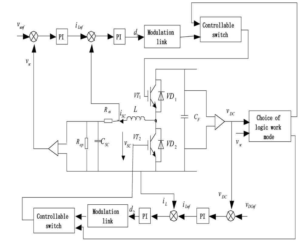
Figure 2: Control diagram of a bidirectional DC/DC converter 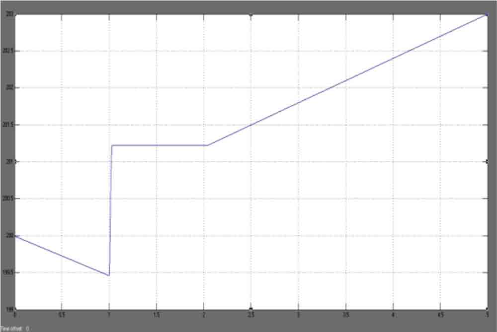
Figure 3: A waveform of the super-capacitor voltage 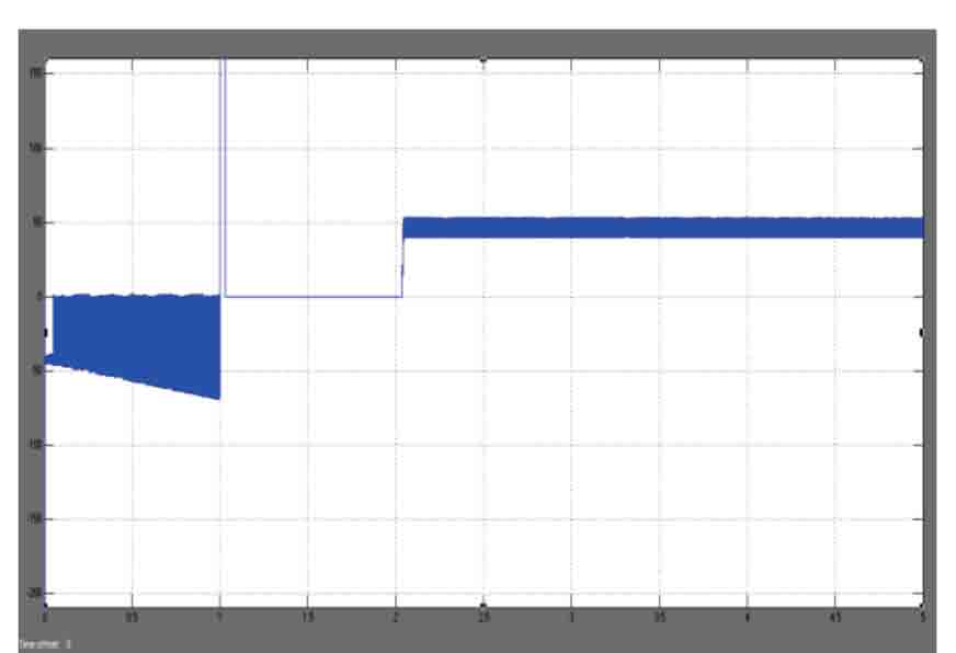
Figure 4: A waveform of the DC bus voltage 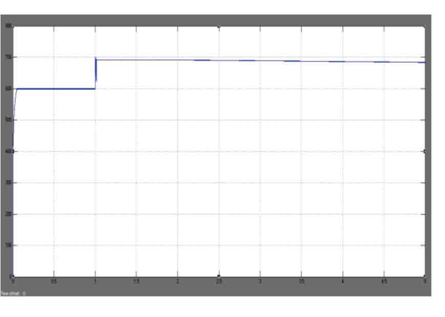
Figure 5: A waveform of the charge/discharge current 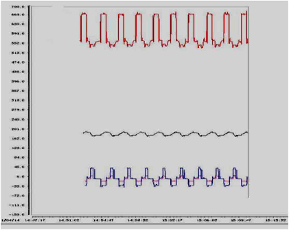
Figures 6: Waveforms for (top to bottom) DC bus voltage, super-capacitor voltage and super-capacitor charge/discharge current under no load 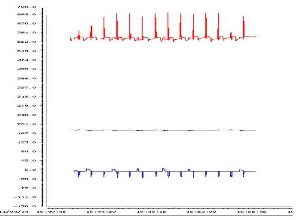
Figure 7: Waveforms for (top to bottom) DC bus voltage, super-capacitor voltage and super-capacitor charge/discharge current of super capacitor under half load
Get more of Elevator World. Sign up for our free e-newsletter.


