Software Testing of Embedded Safety Loops
Nov 1, 2013
by Alexandru Forrai and Takaharu Ueda
This article deals with hardware-in-the-loop (HIL) software testing applied to programmable electronic safety systems (PESSes) used in passenger elevators. Development of PESSes with application in elevators and escalators started in the early 2000s. Electronic overspeed governors, detection of uncontrolled car movement and two elevator cars in one shaft are examples of applications in which PESSes are already in use or can be used in commercial solutions. Although they will not replace incumbent mechanical safety systems in the near future, they may enhance passenger safety and lead to cost reduction.
Also called “embedded safety systems,” PESSes have two main parts: hardware and software. These are not separable and are equally important. The hardware shall be developed to fulfill the required Safety Integrity Level (SIL). In this sense, safety-loop probability of failures per hour due to random hardware failures is calculated, and the SIL level is assessed.
Since embedded safety loops rely on the software, too, we will mainly discuss systematic software development, focusing on HIL software testing. One of the main goals of the software is to reduce systematic failures by using a proper software development cycle. Software failures belong to the category of systematic failure, though they might appear random.
The safety loop can have many applications in the industry using only a few simple hardware components, such as a thermistor, relay or limit switch. However, there are applications that cannot be immediately switched off in the case of an emergency, requiring an intelligent safety loop. Such safety loops can be realized using embedded hardware/software and shall be developed according to such industry-relevant safety standards as IEC 61508.
The structure of a simple embedded safety loop is shown in Figure 1. It has three main components: sensor, embedded safety system and actuator. When the safety function is triggered, the equipment is switched either into a safe state or off. A dual-channel architecture of the safety loop may be necessary to achieve a higher SIL.
In many industrial applications, an intelligent safety loop that can differentiate among severity of faults and emergency levels is desired.[1] For example:
- If a minor fault occurs, a warning is issued, and the process can still run for a limited time.[2]
- If a major fault occurs, a warning is issued, and the process switches to a safe mode and runs for a limited time.[3 & 4]
- If the safety function is triggered or the emergency button is pressed, the process switches to a safe state or is switched off immediately.[5 & 6]
Such intelligent safety systems can be realized using embedded software. Thus, the proper functioning of the safety systems is dependent on the proper (error-free) functioning of the software.
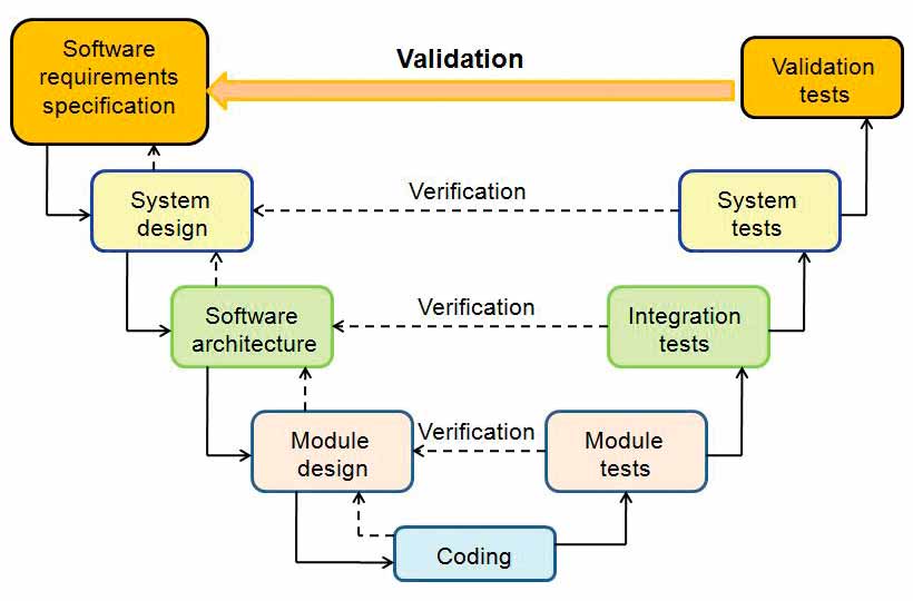
In most cases, the software development process follows a so-called “V-model” (Figure 2). For each design phase, there is a corresponding verification (testing) phase.
Testing
Nowadays, software is present in all major industry sectors and plays an important role in our daily life. In some applications, the software is not safety critical, so its failure will not endanger lives. In applications, where the software is safety critical, it shall be developed according to industry standards. Despite it being extensively tested, failure is still possible. Therefore, testing plays an important role in software development. Early detection of software errors can save costs and significantly reduce development time.
Since software development is usually an iterative process (requirements can change or new requirements might be defined), it is highly recommended to apply test automation. For every new software version, previous tests (regression tests) have to be rerun to ensure the new changes have not introduced errors. Test automation has several advantages, such as:
- More testing can be completed in less time.
- Many test cases can be executed without human intervention.
- Tests cases are valuable; once they are created, they can be reused.
Software testing methods are grouped into different categories based on different criterion. Testing methods – depending upon whether the software under test is executed or not – can be divided into two categories: static and dynamic.
Static Testing
Static testing is a method by which the software code is inspected, but the code is not run. It is mainly a syntax checking of the code and/or manual review of the code or document to find errors.[7]
Code reviews, code inspection and walkthrough fall into the category of static testing. Formal code inspections are probably the most important tool to quickly reduce software bugs. The code inspection is based on the idiom “two heads are better than one.” For example:
- IBM found inspection gave a 23% increase in productivity and 38% reduction in bugs detected after unit test.[7]
- Hewlett-Packard found that 80% of the errors detected during inspection were unlikely to be caught by testing.[7]
Although code inspection may take up to 20% longer, debugging can shrink by an order of magnitude. There is no known better way to find bugs than through code inspections.[7]
Dynamic Testing
Dynamic testing is a software testing method by which the software under tests is complied and run. The term refers to working with the software: giving input values and checking if the output is as expected. Unit tests, integration tests, system tests and acceptance tests are some of its methodologies. Furthermore, depending upon whether the internal structure of the software code is accessible, testing methodologies are divided into black- and white-box testing.
Black-Box Testing
Black-box testing is a software testing method that does not require specific knowledge of the internal structure of the software code. Test cases are derived based on defined requirements and specifications. These tests can be done at all software testing levels: unit, integration, system and acceptance. In most of the cases, it is a functional test, so it is mainly used at higher testing levels, though also done at the unit testing level.
White-Box Testing
White-box testing is a software testing method that requires access and knowledge of the internal structure of the software code. The code is instrumented, and the software tester chooses inputs to exercise paths through the code and determines the correct output. In most cases, this is done at unit level, but it is possible to perform it at the integration and system levels, too. It is a very effective method by which to detect software errors, but it might not detect missing requirements or unimplemented parts of the specifications.
Testing Overview
Software testing is a time-consuming and costly process. In the aim to make software testing effective, test strategies shall be defined and should be used to derive test cases (suites). Moreover, software testing metrics (such as code coverage) shall be used to analyze the adequacy of the defined test suites. The code-coverage model defines the parts of an implementation that shall be executed during the tests. The coverage is a metric (usually expressed in percentage), defined as a ratio between the executed code parts and the defined parts to be executed, according to the coverage model. To derive the testing coverage, the code shall be instrumented: it will require access to internal structure of the software code.
If we represent the software as an oriented graph (Figure 3), we can show it is better to test two software paths 50 times each than to test only one path 100 times. If we think about real-time embedded software, such as that which runs in elevators and escalators, we can observe that most of the unit and integration software tests do not take place in real time.
Software tests in real-time are usually done at the system test level in a late stage of development – i.e., in the elevator test tower. It would be desirable to perform and repeat such tests at an earlier stage to reduce development time and increase software quality. Therefore, we will focus on HIL software testing.
HIL Software Testing
The basic idea of HIL is to replace the real system by a real-time plant model (Figure 4), which is running on the hardware in real time. In other words, our elevator in the test tower is replaced by a real-time elevator model running on the hardware. The embedded system under test (which, in our particular case, is the embedded safety loop), connected to the HIL can be tested in the same way as in the real test tower. Thus, tests performed using HIL should be very close to tests performed in the real system.[8 & 9]
Obviously, tests performed in the HIL cannot replace
the tests performed in the test tower, but they can allow easy performance and repetition of similar tests in an earlier stage of development. HIL tests are situated somewhere between integration and system tests and belong to the category of functional testing/black-box testing.
Since code-coverage models are mainly defined in white-box testing methods, in the case of HIL, such a coverage model is not available. Despite this, it would be very useful to also define a test coverage model in HIL testing. Therefore, let us introduce the HIL software testing metric via an example, considering the safety system of an elevator shown in Figure 5. The elevator is driven by a motor, and if the overspeed limit is exceeded (dashed line in Figure 5), the safety function is triggered: the motor is switched off, the safety relays open the safety line, and the brakes are released. The speed during normal operation for different position values is marked by the solid line. The overspeed limit is defined for different position values, so our embedded safety loop basically resembles an overspeed governor and a smooth terminal slowdown.
A possible structure of the embedded safety loop is shown in Figure 6, where the speed and position information is provided by a dual-channel encoder. A similar hardware structure[4] and safety timer[2] are noted for reference.
The speed information is represented on 2 bytes, and the position information is on 4 bytes and sent to the embedded safety system using the CANopen safety-communication protocol. Two proximity switches, denoted by limit switch 1 and limit switch 2, which provide information about the two extreme positions, are wired to the embedded safety system. The embedded safety system contains two safety relays, which open the safety line if the safety function is triggered or an error is detected in the safety loop.
The state transition diagram, with the main states of the safety loop, is shown in Figure 7. For simplicity, the safety loop presented here is fully independent of the elevator/escalator control system. This means it is not an intelligent safety loop: even a minor internal fault will trigger an emergency stop, which might not be desired in practice.
The state transition diagram presented in Figure 7 allows us to represent it as an oriented graph (Figure 8). This will allow us to introduce a software-testing metric (state transition path coverage) even in case of HIL tests. If all the paths are exercised (Figure 8, bottom) considering the whole sets of events/errors, we can say that HIL tests achieve 100% testing coverage. The oriented graph is very simple, having only two paths. However, in case of an intelligent safety loop, it will become more complicated, and the testing metric introduced for HIL tests will make sense. In functional tests (HIL falls into this category), the state transition diagram is known, although the software code is not accessible.
HIL Experimental Setup
A simple, cost-effective HIL test environment has been built around National Instruments’ Compact RIO™ hardware (Figure 9). A simplified elevator model is implemented in real time on the hardware. The user interacts with the HIL via a graphical user interface that runs on a personal computer.
Some of the main requirements imposed on the HIL test environment are:
- Reproduce normal operating conditions of the elevator
- Create overspeed conditions
- Inject different errors (Figure 10) into the safety loop
Automate the tests
The following injected errors should be considered during testing of the safety loop. Internal failures of the embedded safety loop, such as watchdog-timer failure, central-processing-unit frequency drift and safety-timer failure can be injected via HIL only if the hardware of the safety loop allows access to these devices. Memory errors can be injected only if the software of the safety loop can be modified; therefore, this is not considered a typical HIL test.
Some experimental results are shown in Figures 11 and 12. In the latter, the overspeed condition is detected by the safety loop, and an emergency stop is generated (brake trigger signal on left).
Conclusion
HIL is an effective embedded-system test environment in general, for embedded safety loops in particular. It is widely used in different industrial sectors, the automotive industry being one of the frontrunners in this sense. In our case – depending on the complexity and accuracy of the real-time model – a so-called “virtual elevator in a virtual shaft” can be realized.
The presented embedded safety loop – by software parameterization – can be applied for a wide range of elevators, having different nominal speeds and different travel lengths. The HIL test environment is a very effective tool for testing such a safety loop for the following reasons:
- The full application range can be effectively tested.
- Different faults can be injected easily and more efficiently.
- Test scenarios, which are difficult to realize in the test tower, can be easily realized in HIL.
- Tests can be repeated easily.
- Design issues and software errors can be detected in an early phase, and software quality can be improved.
- Software validation time becomes shorter, which means lower development costs and lower costs to innovate.

Figure 1: Embedded safety loop 
Figure 3: Test coverage versus number of tests 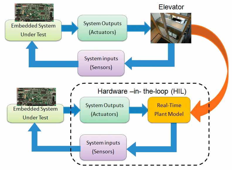
Figure 4: The concept of HIL 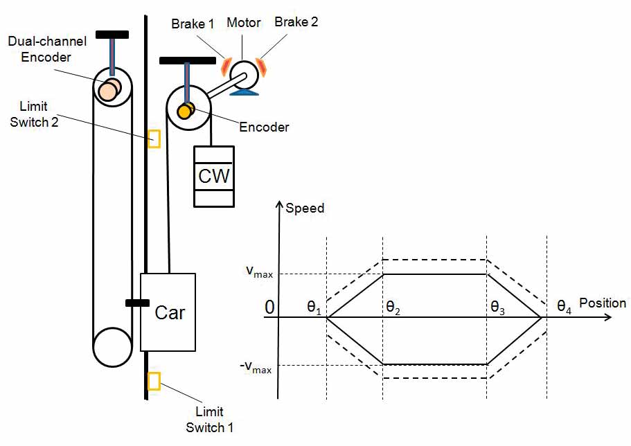
Figure 5: Elevator drive and region of safe operation 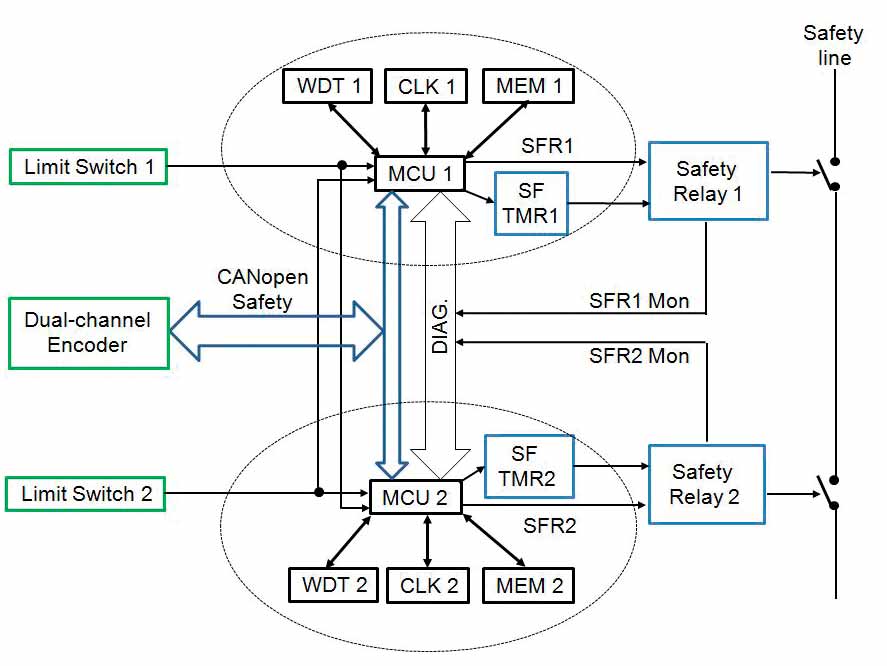
Figure 6: Dual-channel embedded safety loop 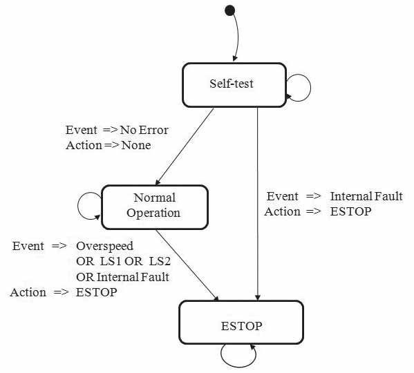
Figure 7: State transition diagram of the safety loop: “LS” stands for “limit switch.” 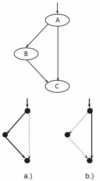
Figure 8: Oriented graph and possible paths of the state transition diagram 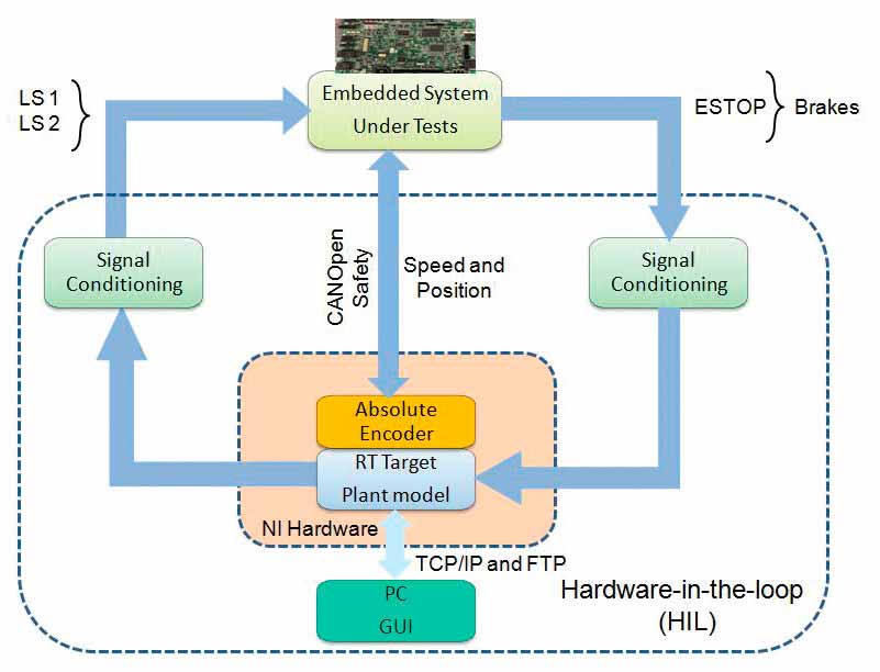
Figure 9: The structure of the HIL test environment built around Compact RIO 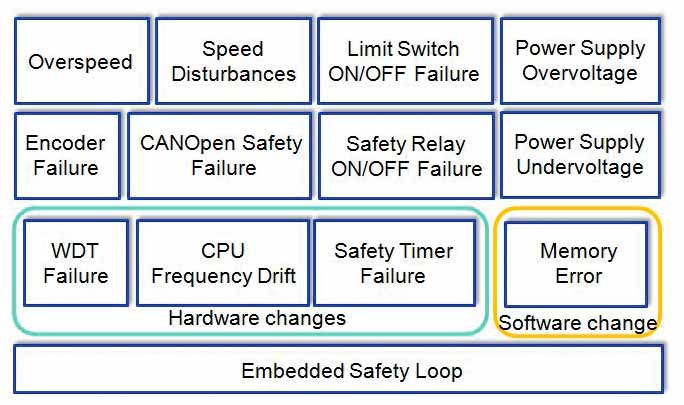
Figure 10: Test categories defined for the safety loop 
Figure 11: Test category: normal operation 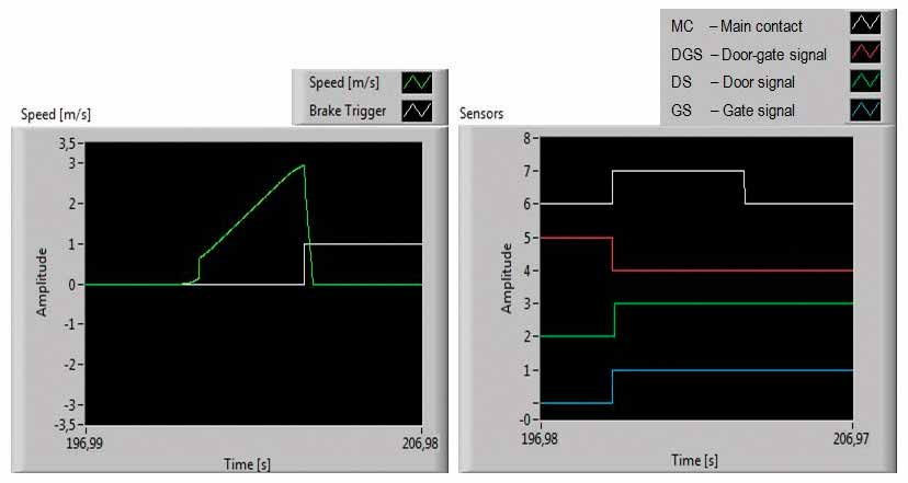
Figure 12: Test category: ascending car overspeed condition generating using HIL
References
[1] R. Isermann: “Mechatronic Systems — Innovative Products with Embedded Control.” Control Engineering Practice 16, p. 14-29, Elsevier (2008).
[2] L. Al-Sharif, K. Seaborne and D. Austin: “Electrically Based Intelligent Escalator Braking Systems.” Proceedings of Elevcon 2010, A. Lustig (Ed.) p. 1-15 (2010).
[3] A. Chida, T. Matsuoka, K. Okamoto and T. Kugiya: “Development of an Electronic Safety System for Elevators.” Proceedings of Elevcon 2006, A. Lustig (Ed.) p. 1-9 (2006).
[4] R. Kondo, H. Kigawa, T. Ueda, M. Shibata, J. Hashimoto, A. Chida and H. Marumo: “Development of Brake Control System for Elevators.” Proceedings of Elevcon 2010, A. Lustig (Ed.) p. 194-203 (2010).
[5] M. Erndl: “Use of Electronic Systems for Safety Components in Elevators.” Proceedings of Elevcon, A. Lustig (Ed.) p. 68-78 (2008).
[6] H. Koenig: “Safe Operation of an Elevator Drive without Motor Contactors.” Proceedings of Elevcon 2010, A. Lustig (Ed.) p. 186-193 (2010).
[7] J. Ganssle: The Art of Designing Embedded Systems — 2nd Ed. Elsevier Inc. (2008).
[8] M. Schlager, R. Obermaisser and W. Elmenreich: “A Framework for Hardware-in-the-Loop Testing of an Integrated Architecture, In Software Technologies for Embedded and Ubiquitous Systems.” Lecture Notes in Computer Science, Springer, Vol. 4761, p. 159-170 (2007).
[9] A. Forrai: Embedded Control System Design – A Model Based Approach. Springer Verlag (2012).
Get more of Elevator World. Sign up for our free e-newsletter.


