Solving Hydraulic Elevator Heat Issues: Targeting the Root Cause
Jun 1, 2013

Elevator mechanics frequently deal with a fair share of heat issues in hydraulic elevator systems. The key to solving these issues is targeting the root cause, not a symptom. The difference between the two approaches is getting the job handled the first time, versus the likelihood of a costly return call from an unhappy customer. Addressing the root cause is the only way to be sure the heat issue has been removed for the long term.
Causes
Return calls will eat a company’s bottom line and damage its credibility, so this article will begin by identifying the most common root causes for heat issues:
- Wrong elevator for the job or traffic flow
- Machine-room ventilation
- Power-unit tank placement
- Pressure drop (friction in the system)
- Valve adjustment (time spent in up leveling and oil viscosity relating to temperature during valve setup)
Often, buildings change hands, and their use evolves over time making the original design and equipment obsolete. In these cases, the wrong elevator for the job or traffic flow may exist. Everything with this hydraulic elevator could be working as intended, but the traffic flow and use has increased to a level beyond its capacity, resulting in heat issues. So, that leaves the building owner with a decision: replace it with appropriate equipment or add an additional elevator to share the load.
Another common root cause is not allowing for proper machine-room ventilation. Hydraulic elevators produce heat, and if that heat is not exhausted, it will build on itself and develop into heat-related performance problems. The culprit here is most common to remodels, where a nonventilated room/closet is made into a machine room. This situation results in stagnant air that contains and builds heat.
A second problem to using a room/closet for a machine room in a remodel is the lack of adequate space that forces the placement of the power-unit tank in a corner, against the walls (Figure 1). In such a case, two sides of the tank become insulated, taking away half of the tank’s ability to radiate or dissipate heat from the system.
Pressure drop or friction in the system is often overlooked in the design phase of a hydraulic system. Many contributing parts/components affect system friction. These include mufflers, elbows, pipe length and pipe size, tank location, etc. If these factors are not calculated into the system, pressure- and heat-related issues will result. Friction results in wasted energy (not applied to moving the car), which transforms into heat.
The biggest contributing factor to heat issues from the control valve has to do with time spent in up leveling. This is where 80-100% of the oil is bypassing to the tank, and the car is slowing and/or coming to a stop in the up direction with the pump running. Simply, the more time spent in this state, the more horsepower is wasted, generating heat in the system. Most often, this heat issue comes from setting up the valve with cold oil (< 70°F). When the system reaches normal operating temperatures (100-120°F) during the day, the valve reacts faster due to the oil viscosity change (thinning), which leads to longer leveling times, wasted horsepower and heat issues (Figure 2).
Solutions
The following solutions are understood to be applied in conjunction with each other for maximum benefit and with a mechanically sound, running hydraulic elevator.
In our first root cause (wrong elevator for the job), the solutions suggested were to replace the old elevator with more-appropriate equipment or adding another elevator to handle the increased traffic. The mechanic’s job here is to send these solutions up the chain to be dealt with by sales and the building owner. If the building owner decides to keep what is in place, all the mechanic can do is optimize the performance and conditions mentioned in following solutions.
In the second root cause (machine-room ventilation), the solution is to first exhaust the heat as simply as possible. Installation of venting near the ceiling (or, better yet, an exhaust fan with vent) is the simplest and lowest-cost approach. Without exhausting the heat, the following solutions won’t be as effective and could even prove counterproductive. After exhausting the heat, one might choose to install an oil cooler or bring in ventilation and air-conditioning (A/C). Understand that when adding these solutions, energy cost will be higher than just exhausting the heat. Also, if the heat is not exhausted and you add A/C, the cold/heat mixture will generate condensation that will bring additional problems into the system in the form of rust.
The third root cause (power-unit tank placement) can be dealt with in several ways. Move the tank at least 6 in. from all walls to allow natural radiation and heat displacement to occur. If the tank can’t be moved, start by making sure the tank is filled with oil to capacity. The more oil, the more it takes to heat it. In addition to adding oil, install a small fan to circulate the stagnate air between the tank and walls, helping the tank to naturally radiate heat away from the tank. As mentioned earlier, combine with all applicable cooling methods to maximum benefit.
Dealing with the fourth root cause (pressure drop/friction in the system) requires inspecting for all the contributing components that add to pressure drop. Determine if there is a muffler, how many elbows or turns are in the pipe, what length of pipe is used, the pipe size, etc. All these friction points introduce heat into the system. Use Table 1 to determine the total pressure drop in the system. Once you have an understanding of where the system is generating friction, you can make the necessary changes to reduce it.
The fifth root cause (proper valve adjustment/reducing time spent in leveling and oil viscosity relating to temperature during valve setup) can be solved with oil-viscosity education, having the current adjustment procedures for the control valve in place and making the correct adjustments. Always set up the valve at the low end of the operating temperature. Maxton Manufacturing Co. offers several tools to help elevator mechanics with proper valve adjustment using Maxton valves at its website: maxtonvalve.com. For best results when dealing with heat, the valve should be set up in the green range in Figure 3. If the system has large temperature swings, it is best to install a heater that can maintain 100°F, then set up the valve at that established low operating temperature.
By applying this knowledge to all future hydraulic- elevator heat-related issues, you will be well on your way to keeping your bottom line intact and your customers happy.
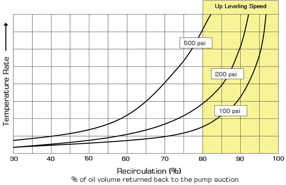
Figure 2 Figure 1
Get more of Elevator World. Sign up for our free e-newsletter.


